


Powered Walk Behind Mower - CE Part No. 04016218 Rev G © Copyright 12/2006
™
8
ENGLISH
MAINTENANCE (Continued)
Drive Chain Adjustment
• Refer to the “Warning” and “Caution” notes at the beginning of the maintenance section.
• Keep the chain correctly tensioned to prevent damage or abnormal wear.
• Do not over tension the chain.
CAUTION
• Ensure the engine and muffler are cold before attempting to adjust the chain to prevent
burns.
WARNING
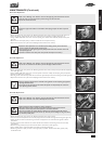
• Remove the drive frame cover (refer to the “Removing the Drive Frame Cover” section) and expose the drive chain.
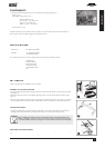
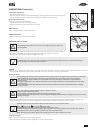
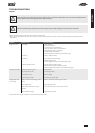
• Using a long slender shaft press firmly on the chain as far from the top sprocket as possible (refer figure 17).
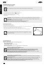
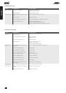
• Using a suitable Phillips head screw driver rotate the adjusting screw until the chain deflection (above) is 5mm (refer
figure 18).
• Rotate the outer clutch plate (chain), recheck chain deflection and re-adjust if necessary.
• Replace the drive frame cover (refer to the “Replacing the Drive Frame Cover” section).
• Rotate the chain adjustment screw clockwise (when looking directly at the head of the
screw) to tighten the chain tension and vice versa.
• Use a very long, or right angle single drive phillips head screw driver to better access the
chain adjusting screw.
• Check the condition of the chain joiner and sprocket and replace if necessary.
Drive Belt Adjustment
• Refer to the “Warning” and “Caution” notes at the beginning of the maintenance section.
• Do not over or under tension the belt to prevent damage or abnormal wear.
CAUTION
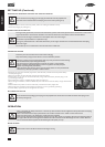
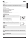
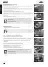
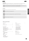
• Remove the drive frame cover (refer to the “Removing the Drive Frame Cover” section) and expose the belt adjustment
screw (refer figure 19).
• Using a suitable phillips head screw driver, screw the adjuster screw down carefully until the spring is fully compressed.
• Unscrew the adjuster two (2) full turns.
• Rock the gear box about the output shaft and it should move approximately 2mm under the spring load (refer figure 20).
• Replace the drive frame cover (refer to the “Replacing the Drive Frame Cover” section).
• Clean any clippings away from the underside of the gearbox near the adjusting spring before
adjusting the belt tension.
• Put a mark on one side of the screw head of the adjuster to easily identify the 2 full turns
when adjusting the belt tension.
Drive Belt Replacement
• Refer to the “Warning” and “Caution” notes at the beginning of the maintenance section.
• Refer to the “Caution” notes in the “Belt Adjustment” section.
CAUTION
• Always wear gloves when handling the cutting mechanism.
• Wear gloves and be aware of pinch points when handling the drive belt mechanism.
• Secure the mower safely when tilted upwards to access the underside.
• Place the rear wheels on support blocks so that the rear extension guard will clear the
ground when lifting the front of the mower up. This will prevent damage to the guard which
is a mandatory safety item.
WARNING
• Remove the drive frame cover (refer to the “Removing the Drive Frame Cover” section).
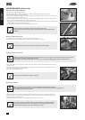
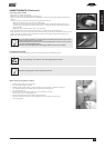
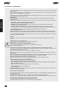
• Unscrew the drive belt adjustment screw until the spring touches the underside of the gearbox housing (refer figure 21).
• Fold the handle bars down and remove the grass catcher and support the rear wheels above the ground on 50mm
(min) blocks.
• Lift the front of the mower about the rear wheels until the lower handle bar contacts the ground and secure safely
in this position.
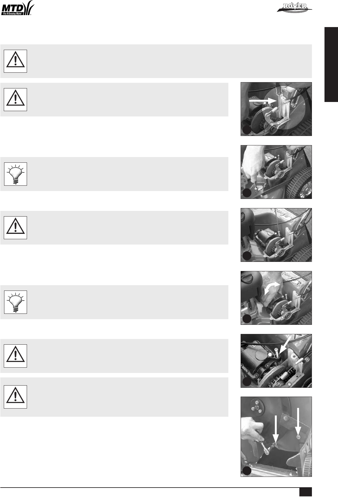
• Rotate the cutting assembly to expose the two bolts which fix the belt cover (refer figure 22).
• Using a suitable spanner, remove both bolts and washers and remove the belt cover.
• Rotate the gearbox so its pulley is as close to the engine pulley as possible. Rotate the belt off the gearbox pulley
and discard the belt.
19
18
20
17
21
22
Powered Walk Behind A4 CE English.indd 11