


Powered Walk Behind Mower - CE Part No. 04016218 Rev G © Copyright 12/2006
™
9
ENGLISH
MAINTENANCE (Continued)
Drive Belt Replacement (Continued)
• Only if the mower is fitted with a full disc and blades will it be necessary to remove the cutting assembly by undoing the
centre bolt and three surrounding bolts with suitable spanners.
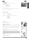
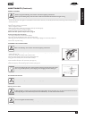
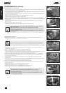
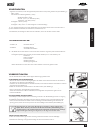
• If the mower is fitted with the “Inline Swing Back Blade” option, rotate both blades backward until the flute on the blade
touches the blade support bar (see figure 23).
• Fit the new belt on the engine pulley, rotate the gearbox so its pulley is as close to the engine pulley as possible. Rotate
the belt into the gearbox pulley groove.
• Adjust the drive belt adjustment screw (refer to the “Drive Belt Adjustment” section.)
• Replace the belt cover, flat washers and bolts and tighten firmly.
• Replace the cutting assembly (where required) and fit the centre bolt and washer and the three surrounding bolts and
washers loosely before tightening in the following sequence and tensions - centre bolt (65-70 Nm) and three surrounding
bolts (16-19Nm)
• If the mower is fitted with the “Inline Swing Back Blade” option, rotate the blades back so they are in line with the
blade support bar.
• Lower the mower so all wheels rest on the ground.
• Replace the drive frame cover (refer to the “Replacing the Drive Frame Cover” section).
• Clean the clipping buildup off the heads of the bolts of the belt cover fixings to ensure the
spanner fits correctly.
• Clean out the belt cover and transmission area thoroughly before reassembly.
• Inspect the drive pulleys for wear, damage and make sure they are not loose while the belt
is removed. Replace as required.
• Special belts and pulleys are used for long life and accurate fitment, so replace with genuine
Rover products.
Adjusting the Drive Clutches
Note: This procedure is only necessary should the drive cable adjustment not be able to provide sufficient drive. This
adjustment is to allow for wear on the drive plates in the long term.
• Refer to the “Warning” and “Caution” notes at the beginning of the maintenance section.
CAUTION
• Remove the drive frame cover (refer to the “Removing the Drive Frame Cover” section) to expose the drive clutch
plates and other adjustments.
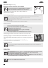
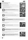
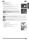
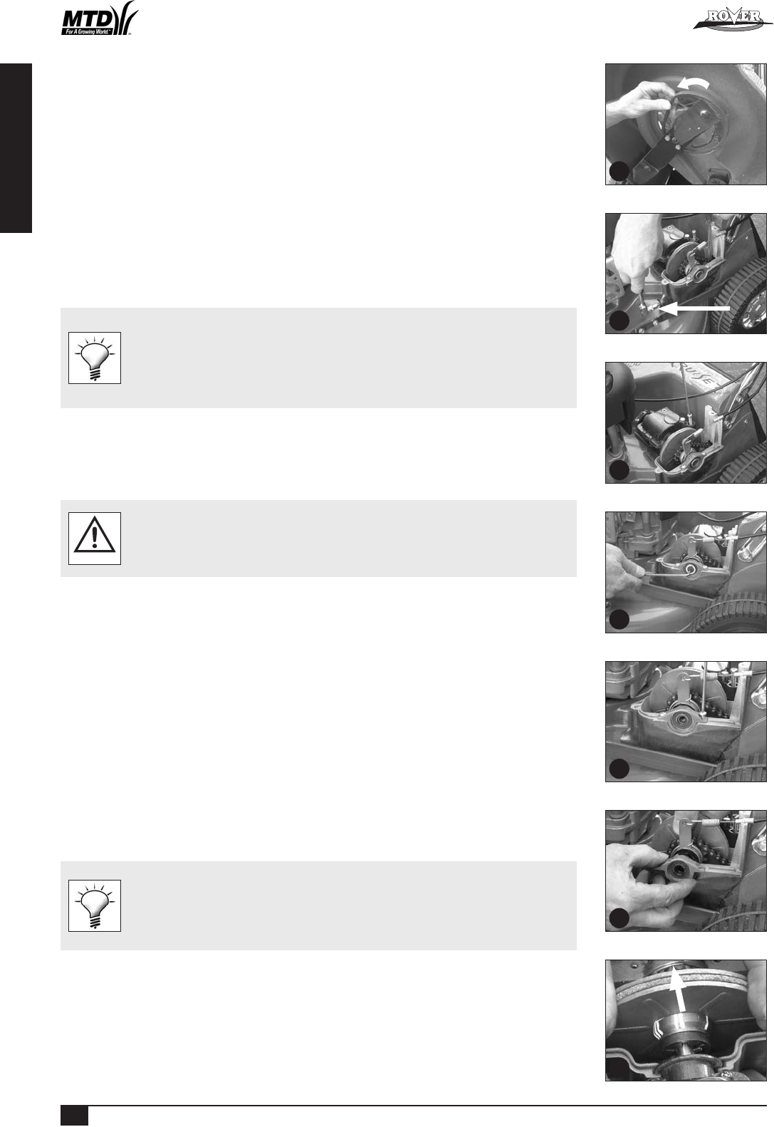
• Loosen the drive chain fully by unscrewing the chain adjuster (refer figure 24).
• Loosen the drive belt fully by unscrewing the drive belt adjuster (refer figure 25).
• Using a suitable Allen key, remove the centre fixing and thrust washer from the end of the output shaft (refer figure 26).
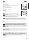
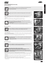
• Remove the two fixings retaining the outboard output shaft bearing housing (refer figure 27).
• Lift the outer end of the output shaft slightly and slide off the outboard output shaft bearing retainer (refer figure 28).
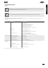
• Take note of which marking (on the boss of the inner drive plate) aligns with the end of the locking roll pin (through
the output shaft) (refer figure 29).
• Move the drive plates and actuating cam in an outboard direction until the inner drive plate is free of the roll pin
(refer figure 29).
• Rotate the inner driver plate until the roll pin aligns with the marking with ONE extra groove than that originally noted
above. Slide back to lock the drive plate to the roll pin into its new position.
• Replace the outer output shaft bearing retainer and screw down firmly in position.
• Replace the centre fixing and thrust washer on the end of the output shaft, apply thread locking solution to the centre
fixing and tighten firmly.
• Readjust the drive chain (refer to the “Drive Chain Adjustment” section).
• Readjust the drive belt (refer to the “Drive Belt Adjustment” section).
• Replace the drive frame cover (refer to the “Replacing Drive Frame Cover” section).
• Re-adjust the clutch cable (refer to the “Adjusting the Drive Cable” section).
• The marks on the inner drive plate boss represents positions ‘1’, ‘11’, & ‘111’. Setting ‘1’ is
generally used with a new drive plate whereas position ‘111’ is for a worn unit.
• If the drive cable adjustment is insufficient with the inner drive plate in position ‘111’ the
drive plates must be replaced.
• Clean off and apply new grease to the cams of the outboard output shaft bearing retainer
and cam lever before reassembly.
25
26
24
27
28
29
23
Powered Walk Behind A4 CE English.indd 12