


Powered Walk Behind Mower - CE Part No. 04016218 Rev G © Copyright 12/2006
™
7
ENGLISH
MAINTENANCE (Continued)
Adjusting the Drive Cable (Continued)
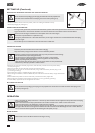
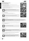
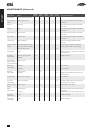
• Start the mower in the disengaged position.
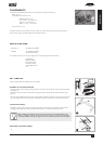
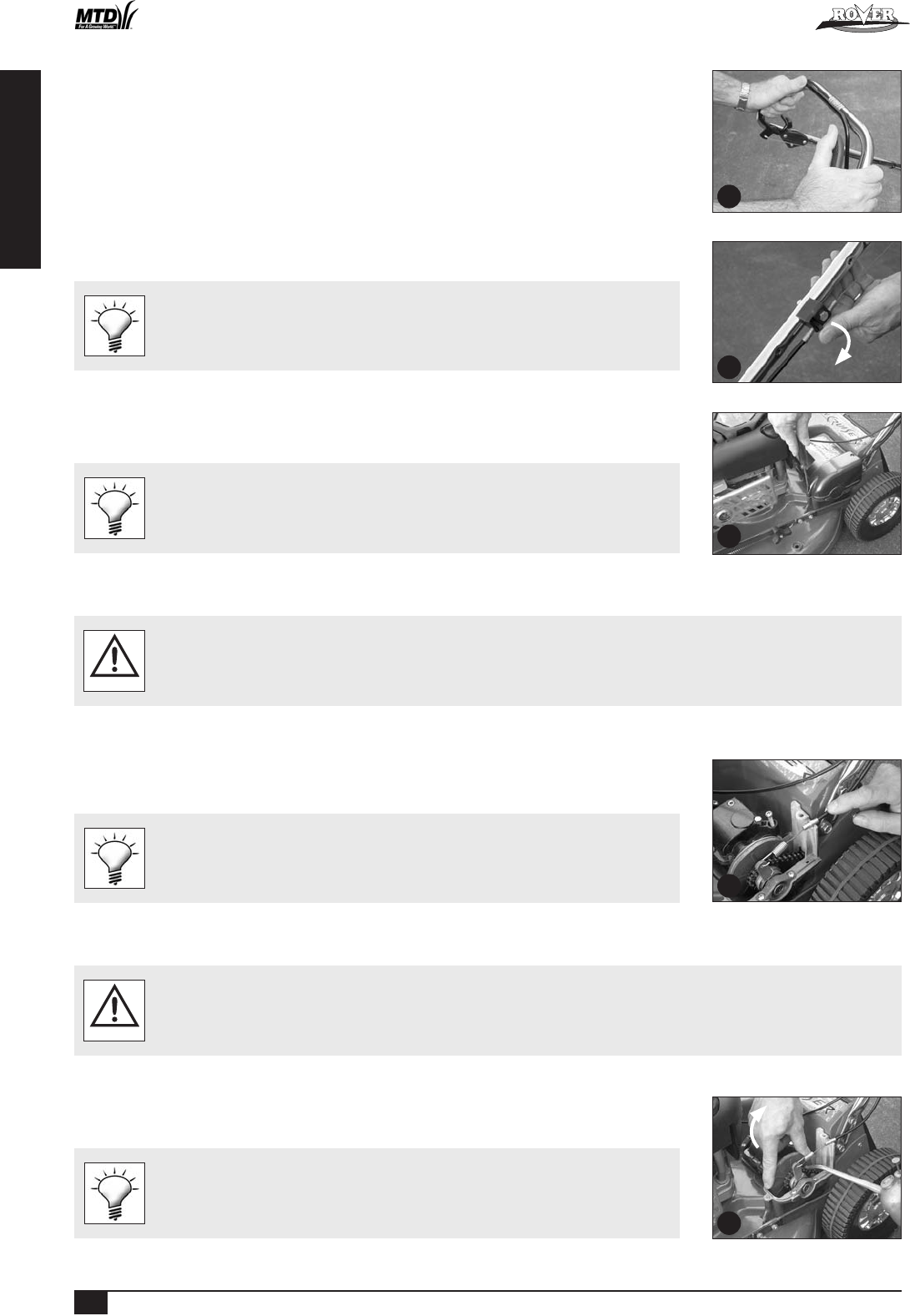
• Push the drive bale forward until the gap between the bale and the handle bar is 55mm (refer figure 12).
• The drive should just begin to engage at this point.
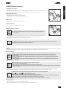
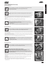
• If the drive is not beginning to engage, rotate the thumb wheel on the cable support block (one click at a time) in an anti
clockwise direction until it does (refer figure 13).
• If the drive engages and drives off at a gap greater than 55mm rotate the thumb wheel on the cable support block one
click at a time in the clockwise direction until it does (refer figure 13).
• Test the mower at all speeds ensuring that it self disengages when the drive bale is released and that the transmission does
not slip at full speed with the drive bale fully engaged.
• If you still experience problems, see your nearest authorised Rover dealer.
• Ensure the cable is not damaged or kinked which may affect the drive.
• Apply a drop of lubricant to the pivot points of the drive bale to ensure smooth and safe
operation.
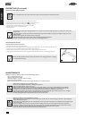
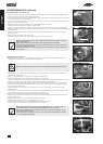
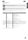
Removing the Drive Frame Cover
• Unscrew the front and rear phillips head screw in that order (refer figure 14).
• Lift the cover and rotate out of the mower to expose the upper transmission components.
Blow grass and dirt out of the recessed holes to expose the head of the fixings.
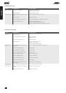
Replacing the Drive Frame Cover
• Make sure the raised ring on the brass section of the drive cable nests into the groove of the lower drive support frame and fit the
lid accurately on top before screwing down the cover.
• Do not operate the transmission bale with the cover loose or removed as you will damage the lower drive support frame.
CAUTION
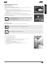
• Fit the drive cable into its retaining slot in the lower drive support frame and hold it down horizontally with one hand
(refer figure 15).
• Rotate the cover into position over the cable until it seats properly and maintain pressure on the lid above the cable.
• Screw the rear fixing above the cable down firmly.
• Screw the forward fixing down firmly.
Leave the fixings in the lid when removing or replacing.
Drive Chain Lubrication
• Refer to the “Warning” and “Caution” notes at the beginning of the maintenance section.
• Do not apply excessive lubricant to the chain as it may flick off and onto the drive clutches during operation.
• Keep lubricant clear of the drive clutches.
WARNING
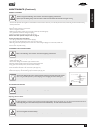
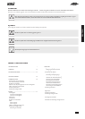
• Remove the drive frame cover (refer to the “Removing the Drive Frame Cover” section) to expose the drive chain.
• While rotating the outer clutch plate (clockwise) apply an even spread of suitable (non aerosol) chain lubricant along
the length of the chain (refer figure 16).
• Replace the drive frame cover (refer to the “Replacing the Drive Frame Cover” section).
Put the chain lubricant in a container with a long pointed spout to make application easier.
Apply a little of the lubricant on the cams between the clutch engagement lever and the
outboard output shaft bearing retainer while lubricating the chain.
16
15
14
12
13
Anti-clockwise
Powered Walk Behind A4 CE English.indd 10