


Ridge Tool Company
31
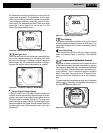
Operating Screen
The display screen of the instrument as seen when locating. It includes an Active View area, where
Tracing and Distortion lines appear in Line Trace modes and where Pole and Equator icons appear in Sonde mode. It also
includes Measured Depth, Signal Strength, Signal Angle, current and Proximity Signal values depending on the mode and
choice of options in use.
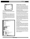
Passive Line Tracing
A mode of tracing a line which does not use a transmitter to place current on the line. It is used
when tracing lines that have externally coupled signals.
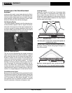
Pole
Where the field lines from the Sonde exit the ground vertically. One of the two ends of a dipole field, such as the
magnetic field of the Earth, or the field around a Sonde. The NaviTrack II displays a Pole icon when it detects the Poles
of a Sonde.
Proximity Signal
A computed signal which reflects how close the operator is getting to the target utility in Line Trace
modes. It is calculated based on the signal received by the two Omnidirectional antenna nodes of the NaviTrack II.
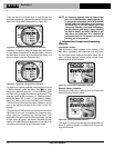
Race Track
An optional circular track around the outside of the Active View Area in which the Level Marker moves to
show current Signal Strength graphically. It also contains the Watermark which shows the highest level of Signal
Strength reached.
Signal Angle
The field angle measured relative to the horizontal plane.
Signal Strength
The relative strength of the total field signal detected by the lower Omnidirectional antenna in three di-
mensions.
Sonde
A self contained transmitter, often battery-powered, which is used to signal a point within an underground pipe,
tunnel, or conduit.
Watermark
An optional display icon which shows the highest level of Signal Strength detected. It travels in the Race
Track and moves up when the Level Pointer reaches a new high point, providing a graphic indication of the highest sig-
nal detected. See Level Pointer.
NaviTrack
®
II