


Ridge Tool Company
27
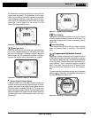
Proximity Signal
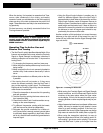
The NaviTrack II’s Proximity Signal is a new piece of in-
formation – a tool to help center the operator on the tar-
get line. It tells the operator how close the instrument is
to the target. Using the Proximity Signal in a locate gives
a more defined peak than using Signal Strength.
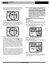
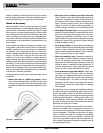
The proximity signal is based on comparing the infor-
mation being sensed by two Omnidirectional antennas in
the upper and lower node casings of the NaviTrack II.
(Active Line Trace and Passive Line Trace modes only).
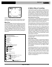
“Informational” Locating
Because of NaviTrack II’s advanced processing and dis-
play, the information provided by the NaviTrack II makes
it clear when a locate has a high confidence level, and
when a locate is suspect.
A good operator can understand the underground picture
with much less effort by using the combined information
provided by:
• Proximity Signal/Signal Strength
• Tracing line and Distortion Line (lower and upper
antennas)
• Continuous Measured Depth indications
• Signal Strength
These indicators show what the antennas are “sensing” as
they move through the field. This signals when a field is
being pulled or pushed out of shape by interference from
other lines or objects nearby. When significant distortion
is present, the indicators will not agree. Knowing distortion
is present allows the operator the option of taking action
to reduce it or at least account for it. (For example, both lo-
cation and Measured Depth reading in distorted fields be-
come suspect).
The other side of having more information is verification
that a locate is good. If all of the indicators are in agree-
ment and reasonable, then the degree of confidence in a
locate can be much higher.
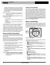
Getting the Most Out Of the
NaviTrack II
The basic features of the NaviTrack II make it quick to
learn. But the instrument also has advanced features
that will make locating in tricky conditions much easier if
the operator understands what they are showing.
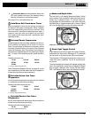
More on Informational Locating
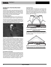
The normal shape of a field around a long conductor
such as a pipe or cable is circular (cylindrical in three di-
mensions). When over the center of a circular field, expect
the following indicators:
• Maximum Signal Strength
• Maximum Proximity Signal (Line Trace Mode)
• Centered Tracing and Distortion lines
• Reasonable and consistent Measured Depth read-
ing
• Minimum Measured Depth
• Sound pitch and volume will increase until they
maximize over the line
The experienced operator learns to “see” the ground sit-
uation by knowing how the different pieces of information
provided by the NaviTrack II relate to each other. While a
simple straightforward locate of a circular field is fast
and easy, tracing a line which is near other large con-
ductors such as power lines, phone lines, gas mains or
even buried scrap metal can lead to questions which
can only be correctly answered by taking all the available
information into account.
By comparing Signal Strength, Signal Angle, Proximity
Signal, Tracing and Distortion lines, and Measured Depth,
an operator can see which way the field is being dis-
torted. Comparing the field information with an educated
view of the ground, noticing where transformers, meters,
junction boxes, manholes and other indicators are lo-
cated can help in understanding what is causing field
distortion. It is important to remember, especially in com-
plex situations, that the only guarantee of the location of
a particular line or pipe is actual inspection, such as by
potholing.
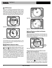
Compound or complex fields will produce different indi-
cations on the NaviTrack II which will show what is hap-
pening. Some examples might be:
• Disagreement between Tracing and Distortion lines
• Inconsistent or unrealistic Measured Depth
• Fluctuating random indications (also caused by
very weak signal)
• Inconsistent proximity signal (line trace mode)
• Signal strength maximizing off to one side of the
conductor
Generally, distortion is likely to be worse at higher fre-
quencies compared to lower frequencies due to the
tendency of higher frequency signals to “jump” to adja-
cent utilities. Large iron and steel objects such as vault
and manhole covers, trench plates, structural supports,
rebar and vehicles can also significantly distort even
the lowest frequencies. In general, passive locating is
more subject to distortion than active locating, espe-
cially in regards to depth measurements. Power trans-
NaviTrack
®
II