


Ridge Tool Company
8
NaviTrack
®
II
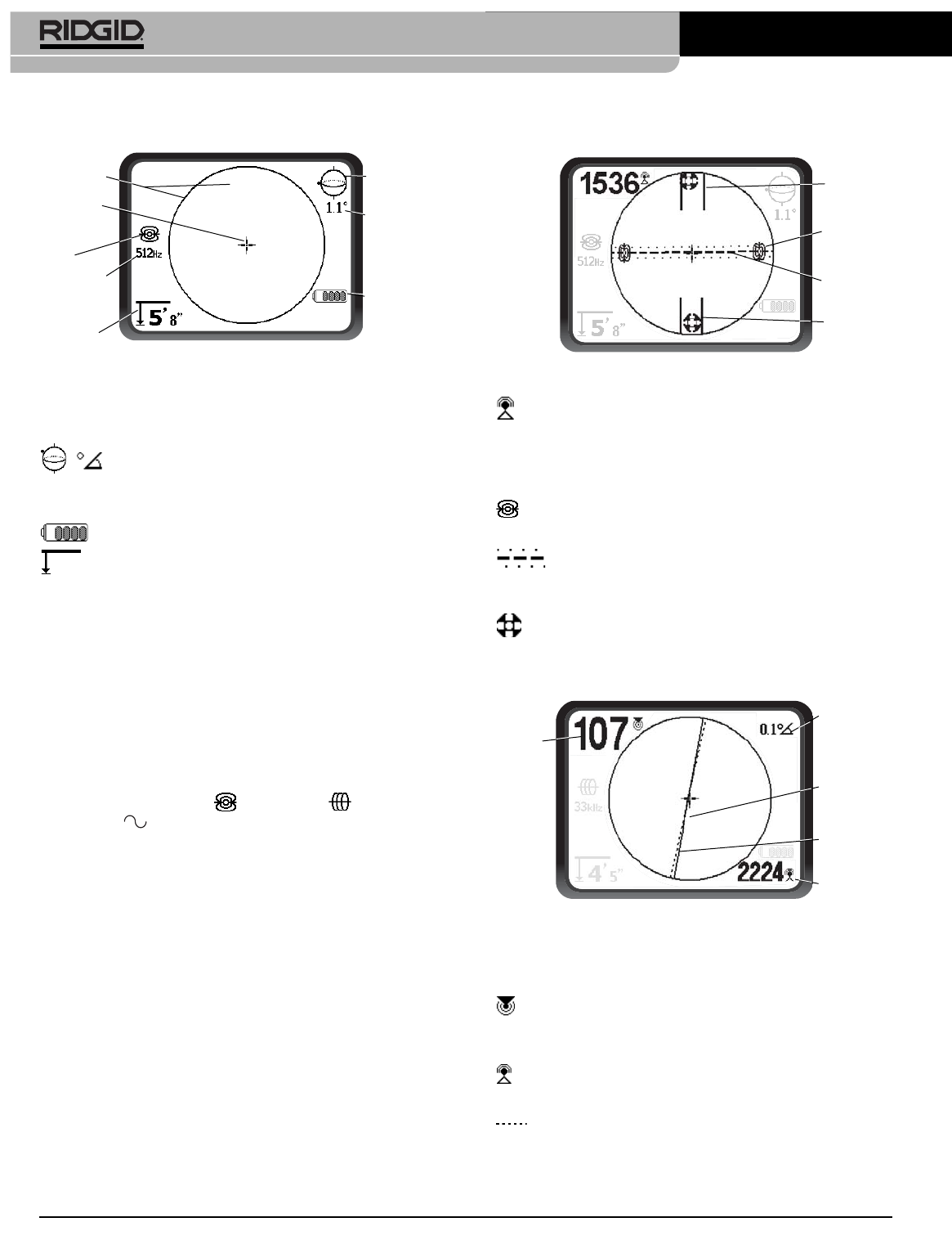
Common Display Elements
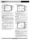
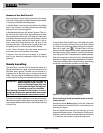
Figure 6 – Common Display Elements
The display screen in Sonde, Active Line Trace or Passive
Line Trace mode will show the following features:
Signal Angle Indicator – Angle toward the
field’s center graphically displayed; numeric value dis-
played below the graphic.
Battery Level – Indicates level of battery power.
Measured Depth/Distance – Displays the mea-
sured depth when receiver is touching the ground directly
over signal source. Displays computed distance when
the antenna mast is pointed at signal source in some
other manner. Displays feet/inches (U.S.A. default) or
meters (European default).
NOTE! Measured Depth is a
computed
number which
may vary from the physical depth or distance
depending on field strength and distortion.
Frequency – Shows current frequency setting in hertz or
kilohertz.
Mode – Icon for Sonde , Line Trace , or Passive
Line Trace mode.
+ Crosshair (Map Center) – shows your position rela-
tive to the target center.
Active View Area – The area within the circle in the cen-
ter of the operating screen, in which Sonde and Pole
icons, Tracing and Distortion lines appear.
Display Elements: Sonde Mode
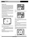
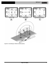
Figure 7 – Display Elements: Sonde Mode
Signal Strength – Strength of signal as sensed by
the lower Omnidirectional antenna.
| | Pipe Direction – Represents the approximate di-
rection of the pipe in which the sonde is lying.
Sonde Icon – Appears when approaching the loca-
tion of a Sonde.
Equator – Represents the mid-line of the
Sonde’s field perpendicular to the axis of the Poles.
(See on page 14.)
Pole Icon – Represents the location of either of the
two Poles of the Sonde’s dipole field.
(See on page 12.)
Display Elements: Active Line Trace Mode
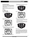
Figure 8 – Display Elements (Line Trace Mode)
In Active Line Trace Mode the following features will
also be displayed:
Proximity Signal – A numerical indication showing
how close the signal source is to the locator. Displays
from 1 to 999 (Line Trace modes only).
Signal Strength – Strength of signal as sensed by
the lower Omnidirectional antenna.
Distortion Line (Upper Antenna Signal) – shows
the apparent direction of the field as detected at the
upper antenna. If out of alignment with the Tracing line,
indicates a distorted field.
Signal Angle
Indicator
Active
View Area
Crosshair
(Map
Center)
Measured
Depth/Distance
Battery
Level
Numeric
Horizontal
Angle
Indicator
Mode
Frequency
,
Pole Icon
Pipe
Direction
Sonde Icon
Equator
Signal Angle
Indicator
Proximity
Signal
Signal
Strength
Distortion
Line
(Dashed)
Tracing Line
(Solid)