


Ridge Tool Company
12
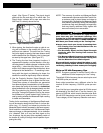
Sounds of the NaviTrack II
The sound level is driven by the proximity to the target.
The closer to the target, the higher the sound pitch will be.
A rising tone indicates increasing signal.
In Sonde Mode, if the sound level reaches its highest
point, it will “re-scale” to a medium level and continue sig-
naling from the new starting point.
In Sonde Mode the pitch will “ratchet” upward. That is, it
will rise and fall in pitch while approaching the Sonde.
Moving away from the Sonde, it will drop to a lower pitch
and remain there as long as one moves away from the
Sonde. Moving back toward the Sonde again it will re-
sume rising and falling starting from the level it had
reached previously. This serves as a guide to when you
are getting closer or further away from the Sonde.
In Line Trace or Passive Line Trace mode, sound is on
one continuous curve and does not re-scale.
If desired, force the sound to re-center at a medium
level (in any mode) by pressing the Select Key during
operation.
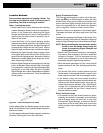
Sonde Locating
The NaviTrack II can be used to locate the signal of a
Sonde (transmitter) in a pipe, so that its location can be
identified above ground. Sondes can be placed at a
problem point in the pipe using a camera push rod or
cable. They can also be flushed down the pipe. A Sonde
is often used for locating non-conductive pipe and conduit.
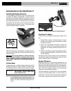
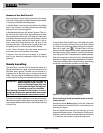
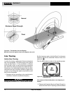
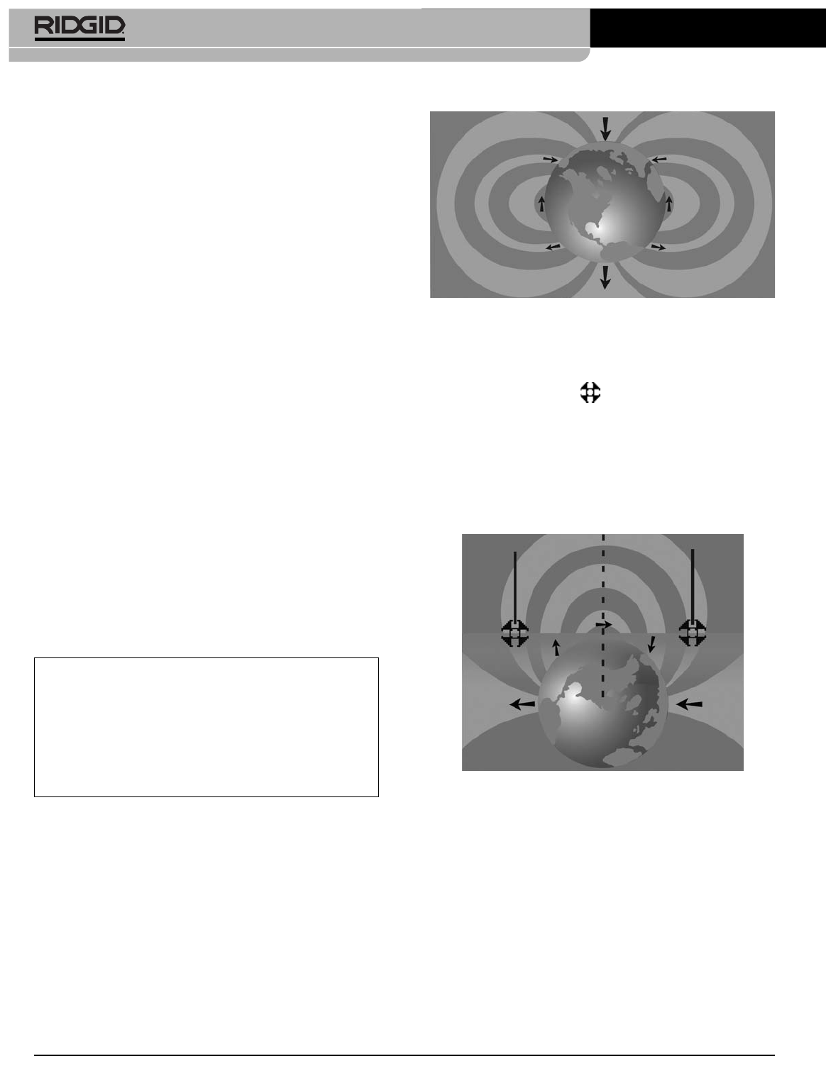
The field of a Sonde is different in form than the circular
field around a long conductor such as a pipe or cable. It is
more like the field around the Earth, with a North Pole and
a South Pole.
NaviTrack
®
II
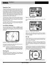
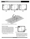
Figure 20 – Earth's Dipole Field
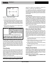
In the Sonde’s field, the NaviTrack II will detect the points
at either end where the field lines curve down toward
the vertical, and it will mark these points on the map dis-
play with a “pole” icon ( ). The NaviTrack II will also
show a line at 90 degrees to the Sonde, centered between
the Poles, known as the “equator”, much like the Equator
on a map of the Earth if the planet were viewed sideways.
Note that because of the NaviTrack’s Omnidirectional
antennas, the signal stays stable regardless of orientation.
This means the signal will increase smoothly approaching
the Sonde, and decrease smoothly moving away.
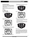
Figure 21 – Earth's Dipole Field Sideways
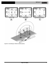
When locating a Sonde set up the locate in the fol-
lowing manner:
Activate the Sonde before putting it in the line. Select the
same frequency on the NaviTrack II and make sure it is
receiving the signal.
After the Sonde has been sent into the pipe, go to the
suspected Sonde location. If the direction of the pipe is
unknown, push the Sonde a shorter distance into the line
(~15 feet from the access is a good starting point).
Pole
Pole
Equator
Ground
IMPORTANT! Signal strength is the key factor in
determining the Sonde’s location. To
ensure an accurate locate take care
to maximize the Signal Strength prior
to marking an area for excavation.
The following assumes that the Sonde is in a hori-
zontal pipe, the ground is approximately level and the
NaviTrack II is held with the antenna mast vertical.
N
S