


Ridge Tool Company
17
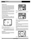
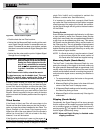
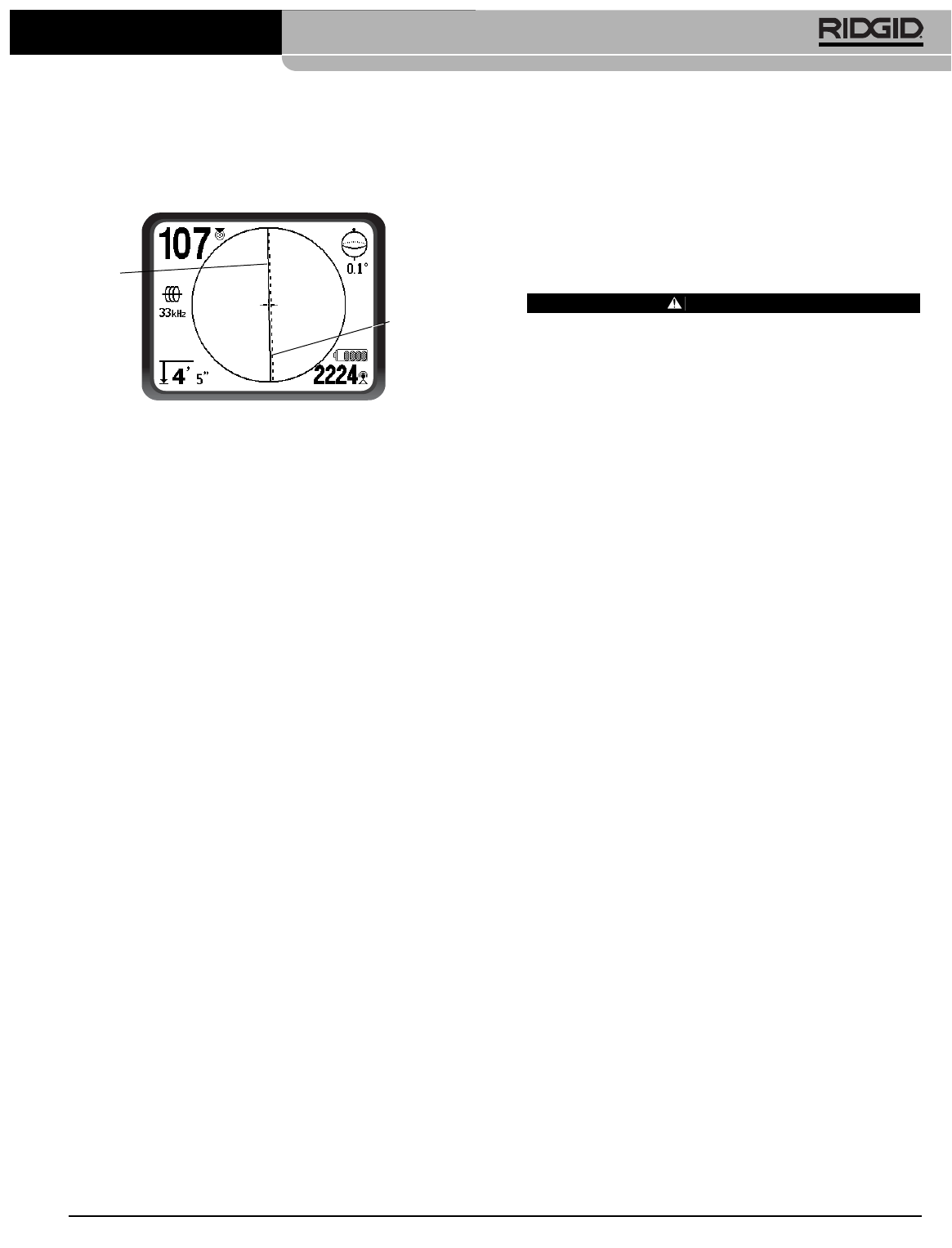
signal.
(See Figure 27 below)
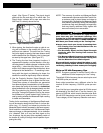
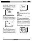
. The signal should
peak over the line and drop off on either side. The
Signal Angle indicator will be near zero when the
NaviTrack II is directly above the line.
Figure 27 – High Probability Locate
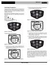
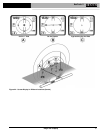
3. When tracing, the direction the pipe or cable is run-
ning will be shown on the screen with 2 lines, one
solid and one dashed. The solid line (the Tracing
line) is the signal as seen by the lower antenna node
and the dashed line (the Distortion Line) is the signal
as seen by the upper one.
(See Figure 27.)
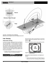
4. The Tracing line has three important functions. It
represents the location, and the direction, of the sig-
nal being traced. It reflects changes in direction of the
target utility — when the utility makes a turn, for ex-
ample. And it helps recognize signal distortion, when
compared to the dashed line — if something is inter-
fering with the signal and distorting its shape, the
dashed line could be significantly offset or skewed.
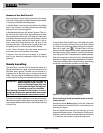
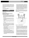
5. Use the Proximity Number, Signal Strength, and
Tracing and Distortion lines to guide the line trace.
These three pieces of information are generated
from discrete signal characteristics to help the oper-
ator discern the quality of the locate. An undistorted
signal emitted from a line is strongest directly over that
line. By maximizing the Proximity Signal, and cen-
tering the Tracing and Distortion lines on the screen
the confidence in a “good” locate is high. Confirm a lo-
cate by testing whether the Measured Depth reading
is stable and reasonable.
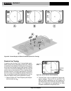
Testing for the consistency of the Measured Depth read-
ing can be done by raising the NaviTrack II a known dis-
tance (say, 12" exactly) and observing whether the
Measured Depth indicator increases by the same amount.
Small variation is acceptable, but if the Measured Depth
does not change, or changes drastically, it is an indication
of a “distorted” field, or a very low level signal on the
line. As always, the only way to be completely certain of
the location of a utility is through visual inspection by ex-
posing the utility.
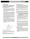
NOTE! The accuracy of position and Measured Depth
measurements improves as the NaviTrack’s low-
er antenna node is placed closer and closer to
the target utility. Rechecking the Measured Depth
and position periodically during the excavation
process can help avoid damage to a target utility
and may identify additional utility signals that
were not noticed prior to excavation.
WARNING
Care should be taken to watch for signal interfer-
ence that may give inaccurate readings. The
Tracing line is only representative of the position of
the buried utility if the field is UNDISTORTED. Do
NOT base your locate solely on the Tracing Line.
Always cross check your locate by ensuring that:
• The Tracing Line and the Distortion Line are
substantially aligned.
• The Proximity Signal and the Signal Strength
maximize when the Tracing Line crosses the
map center.
• The Measured Depth increases appropriately as
you raise the unit vertically and the Tracing Line
and the Distortion Line remain aligned.
Measured Depth readings should be taken as esti-
mates and actual depths should be independently
verified by potholing or other means prior to digging.
Note on 93 kHz Frequency Use
NOTE! European versions of the NaviTrack II offer an
additional 93 kHz frequency for Line Tracing.
The default 93 kHz frequency has an actual cycle count
of 93,696 cycles per second.
Some older transmitters use a different value for the
nominal 93 kHz frequency, 93,622.9 cycles per sec-
ond.
If you find that your transmitter signal at 93 kHz cannot
be detected by the NaviTrack II, set the locator’s fre-
quency to 93-B kHz, which is set to the older value. Both
93 and 93-B frequencies can be found under the Line
Trace category of the Frequency Selection sub-menu.
NaviTrack
®
II
Distortion
Line (Dashed)
Trace
Line
(Solid)