


Ridge Tool Company
20
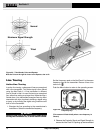
transmitter directly through the air and not from the line
to be traced. To test for air coupling, point the NaviTrack
II directly at the transmitter; if Signal Strength increases,
then the transmitter may be too close to the receiver to
trace accurately.
NOTE! The weaker the inductively coupled signal pro-
duced on the conductor, the greater the air-
coupling distance.
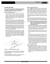
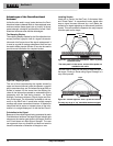
While tracing, the mapping display operates best under
the following conditions:
• The line is level.
• The NaviTrack II Locator is above the target utility
elevation.
• The NaviTrack II antenna mast is held approxi-
mately vertical.
If these conditions are not met, pay close attention to
maximizing Proximity Signal and Signal Strength.
In general, if the NaviTrack II is used in a zone over the
target line within a sweep area of about two “depths” of
the line, the map will be useful and accurate. Be aware
of this when using the map if the target or line is very
shallow. The width of the useful search area for the
map can be small if the line is extremely shallow.
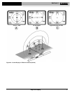
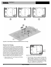
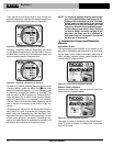
Measuring Depth (Tracing Modes)
The NaviTrack II calculates Measured Depth by com-
paring the signal level at the lower antenna to that at the
upper antenna.
Measured Depth is approximate; it will reflect the phys-
ical depth when the mast is held vertical and the bottom
antenna is touching the ground directly above the signal
source, assuming no distortion is present.
1. To measure depth, place the locator on the ground,
directly above the Sonde or the line.
2. Measured Depth will be shown in the lower left hand
corner of the NaviTrack II’s display screen.
3. A Measured Depth reading can be forced by pressing
the Select Key during a locate.
4. Measured Depth will be accurate only if the signal is
undistorted.
NOTE! In Active Line Trace or Passive Line Trace modes,
pressing the Select Key will force a Measured
Depth reading. If sound is on, it will also re-center
the audio tone.
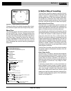
Clipping (Tracing Modes)
Occasionally the Signal Strength will be strong enough
that the receiver will be unable to process the entire
signal, a condition known as “clipping”. When this occurs
a warning symbol will appear on the screen. It
means that the signal is particularly strong and accurate
Measured Depth measurements are not possible. If clip-
ping persists, remedy it by increasing the distance be-
tween the antennas and the target line you are tracing
OR by reducing the strength of the current from the
transmitter. Note that Measured Depth Display is dis-
abled under clipping conditions.
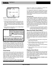
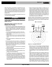
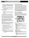
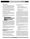
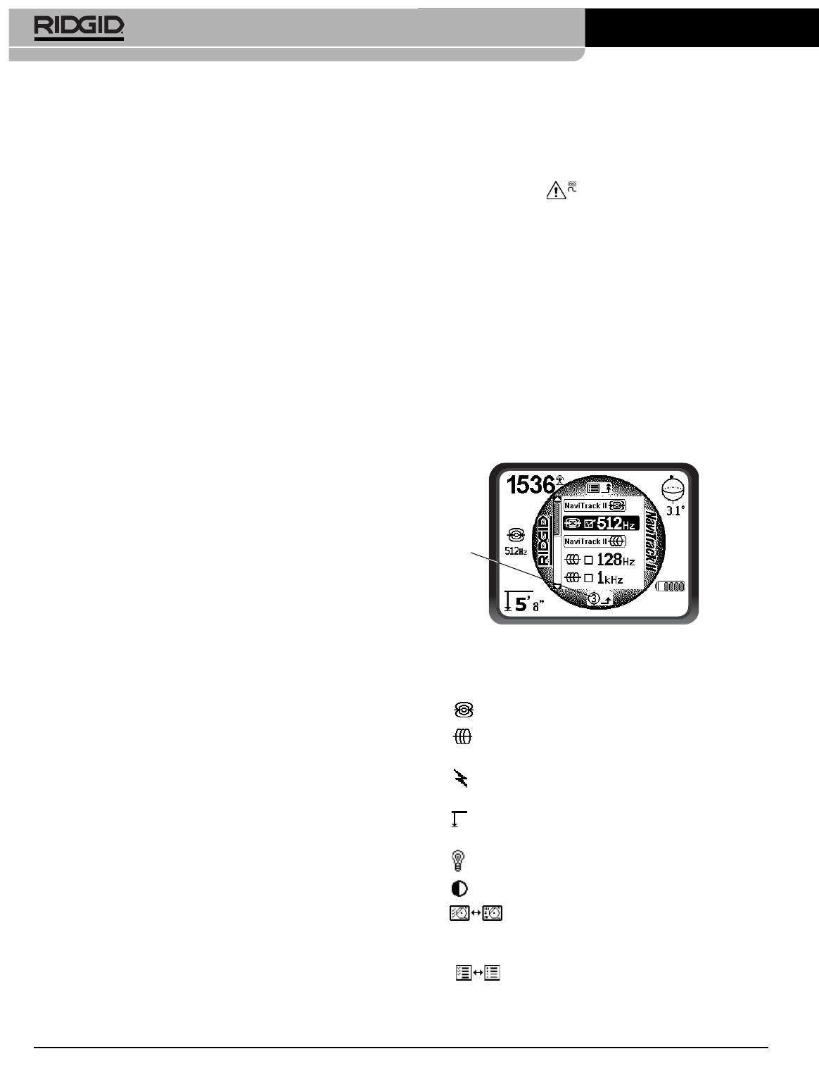
Menus and Settings
Pressing the Menu Key brings up a series of choices
which let the individual operator configure the NaviTrack
II
(See Figure 31).
The menu is a context-sensitive list of
options. The entry point into the menu list is set to the
currently in-use frequency.
Figure 31 – Main Menu
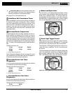
In sequence from the top of the menu down, the Main
Menu presents the following items:
1. Selected Sonde frequencies (activated or not)
2. Selected Active Line Trace frequencies (acti-
vated or not)
3. Selected Passive Line Trace frequencies (acti-
vated or not)
4. Measured Depth Measurement Units Setting
Control
5. Backlight Control
6. LCD Contrast Control
7. Display Elements Control (sub-menus will
display when selected for Sonde or Line Tracing
modes)
8. Frequency Selection Control (sub-menus
will display for categories of frequencies that can be
selected)
NaviTrack
®
II
Auto Menu
Exit
Countdown
Timer