


MITSUBISHI
ELECTRIC
9700 SERIES UPS
OWNERS / TECHNICAL MANUAL
Page Number:
iii
MITSUBISHI ELECTRIC 9700SERIES UPS
List of Figures
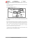
Figure 1.1 Single Line Diagram-Normal Operation ...................................... 1-3
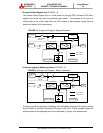
Figure 1.2 Single Line Diagram-Bypass Operation ...................................... 1-4
Figure 1.3 Single Line Diagram-Battery Operation....................................... 1-4
Figure 1.4 UPS Parts Location..................................................................... 1-6
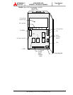
Figure 2.1 Operation/Display Panel ............................................................. 2-1
Figure 2.2 Main Screen................................................................................ 2-3
Figure 2.3 Bypass Screen............................................................................ 2-3
Figure 2.4 Input Screen................................................................................ 2-4
Figure 2.5 Output Voltage Screen................................................................ 2-4
Figure 2.6 Output Current Screen................................................................ 2-4
Figure 2.7 Trend Graph Screen ................................................................... 2-5
Figure 2.8 Battery Screen ............................................................................ 2-5
Figure 2.9 Remote / Local Selection Screen................................................ 2-5
Figure 2.10 Operation Menu Screen.............................................................. 2-6
Figure 2.11 Battery Operation Screen............................................................ 2-7
Figure 2.12 Battery Low Voltage Screen........................................................ 2-7
Figure 2.13 Discharge Termination Screen.................................................... 2-7
Figure 2.14 Fault Indication Screen ............................................................... 2-8
Figure 2.15 External Signal Terminal Block ................................................... 2-9
Figure 2.16 Control Wiring for External Contacts........................................... 2-10
Figure 2.17 Remote "Start" Contact Connections .......................................... 2-11
Figure 2.18 External communication connector............................................. 2-12
Figure 3.1 UPS Terminal Name................................................................... 3-7
Figure 3.2 Diagram of input/output Terminals.............................................. 3-8
Figure 3.3 Start-up Menu ............................................................................. 3-24
Figure 3.4 Inverter Start / Stop..................................................................... 3-24