


MITSUBISHI
ELECTRIC
9700 SERIES UPS
OWNERS / TECHNICAL MANUAL
Page Number:
3
-4
MITSUBISHI ELECTRIC 9700 SERIES UPS
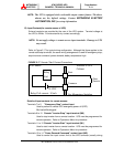
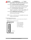
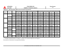
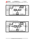
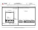
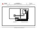
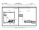
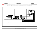
G) Referring to Figures 3.2-a~h, connect UPS load terminals A50, B50, C50 and N50 to
load distribution panel. Refer to Table 3.4 for cable sizes.
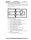
H) Connect external signal terminal block as needed. Refer to section 2.4 and Figure
2.15 for functional description. 12 AWG, or less, shielded conductor is
recommended.
NOTES:
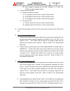
1. Confirm that all UPS internal contactors(breakers) "CB1", "CB2", and
"CB3" are open before energizing UPS.
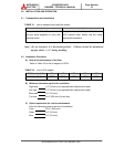
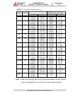
2. UPS power terminals are supplied with bus bar and hardware (12mm
diameter Nut/Bolt assembly). It is recommended that compression lugs be
used to fasten all input/output power cables. Refer to Table 3.5 for
recommended compression lugs and appropriate crimping tool.
3.
If three wire source for input and bypass input is utilized, the neutral
conductor is the UPS must be banded to ground.