


MITSUBISHI
ELECTRIC
9700 SERIES UPS
OWNERS / TECHNICAL MANUAL
Page Number:
2-11
MITSUBISHI ELECTRIC 9700 SERIES UPS
NOTE: The UPS is equipped with a selectable output contact feature. The above
alarms are the default settings. Contact MITSUBISHI ELECTRIC
AUTOMATION, INC. for set-up information.
B) Input Contacts(for remote access of UPS)
External contacts are provided by the user of the UPS system. Terminal voltage at
the UPS is 24Vdc. Provide external dry contact accordingly.
NOTE:
Do not apply voltage to remote access input terminals. Damage to UPS
may result.
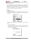
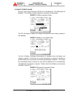
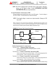
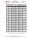
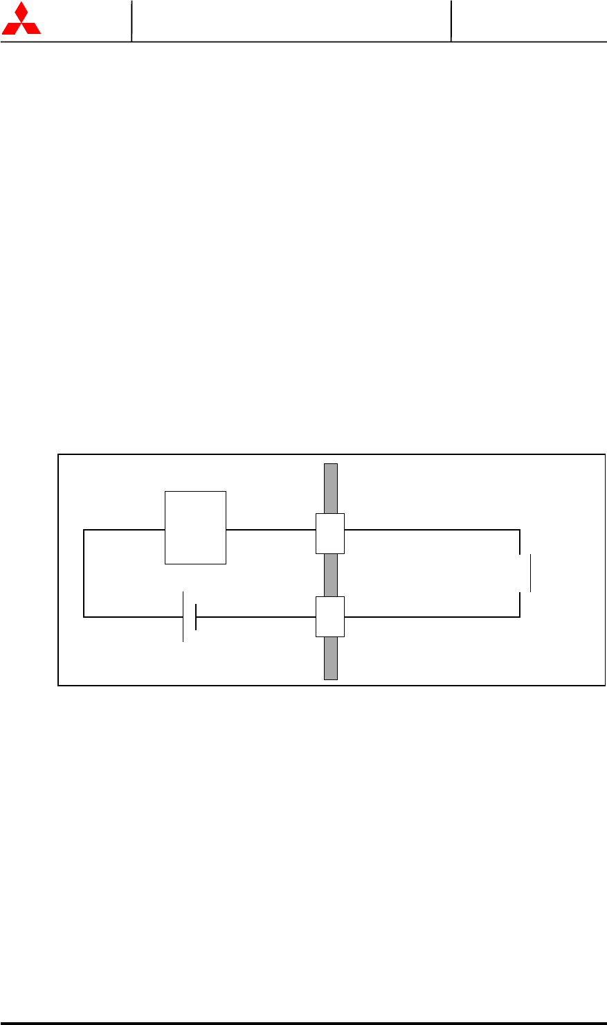
Refer to Figure 2.17 for typical wiring configuration. Although this figure applies to the
remote start/stop terminals, the same wiring arrangement is used for emergency stop;
asynchronous command; power demand; battery temperature high.
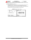
FIGURE 2.17 Remote "Start" Contact Connections
Star
t
Rela
y
Coil current : 8.3mA
Use Momentar
y
Switches
UPS Cabinet External to UPS
Cabinet
Rela
y
Coil
24 VDC
Star
t
Switch
Common
Details of input contacts for remote access :
Terminals 7 to 8 "Emergency Stop" contact input
Used to perform a remote UPS emergency power off (EPO).
The load will be dropped.
Terminals 9 to 10 Remote "Inverter Stop” input terminal (IN0)
Used to stop inverter from a remote location. UPS must be programmed for
remote operation. Refer to Operations Menu for procedure.
Terminals 11 to 12 Remote "Inverter Start” input terminal (IN1)
Used to start inverter from a remote location. UPS must be programmed for
remote operation. Refer to Operations Menu for procedure.
Terminals 13 to 14 "Power Demand Command" contact input (IN2)
Used to control the input current limit to the UPS converter (usually during