


MITSUBISHI
ELECTRIC
9700 SERIES UPS
OWNERS / TECHNICAL MANUAL
Page Number:
2-4
MITSUBISHI ELECTRIC 9700 SERIES UPS
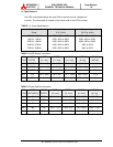
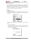
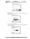
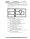
2) Input Voltage and Current (FIGURE 2.4)
The voltages displayed are the RMS AC input voltages (line-to-line) between phases
A-B, B-C C-A and frequency of the AC input line. The RMS values of Phases A, B
and C currents are also displayed.
FIGURE 2.4 Input screen
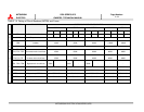
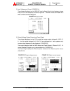
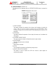
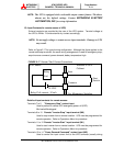
3) Output Voltage, Output Current and Trend Graph
The voltages displayed on the LCD include the inverter output voltages A-B, B-C, C-
A. Line to neutral voltages A-N, B-N, C-N are displayed on 4 wire systems only.
Inverter output frequency is also displayed. (FIGURE 2.5)
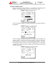
The current displayed and the RMS values and Peak Values of Phases A, B, C. N-
current (Neutral) is display on a 4 wire system only. (FIGURE 2.6)
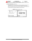
The Trend Graph displays the Effective power values and the Reactive power values.
(FIGURE 2.7)
FIGURE 2.5 Output voltage screen FIGURE 2.6 Output current screen