


MITSUBISHI
ELECTRIC
9700 SERIES UPS
OWNERS / TECHNICAL MANUAL
Page Number:
2-12
MITSUBISHI ELECTRIC 9700 SERIES UPS
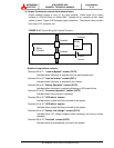
generator operation). Power demand is turned ON when the contact is
closed. Power demand is turned OFF when the contact is open.
Terminals 15 to 16 "Asynchronous Command" contact input (IN3)
Used to create an asynchronous condition between the static bypass source
and the inverter. Asynchronous condition is enabled when the switch is
closed. Asynchronous condition is disabled when the switch is opened.
Terminals 17 to 18 “BATTERY TEMP. HIGH” contact input (IN4)
Input fed by a thermocouple that monitors battery temperature. The
converter float voltage level is reduced for battery over-temperature
conditions. Use battery manufacture recommended thermocouple.
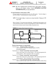
Terminals 19 to 20 “ROOM TEMP. HIGH” contact input (IN5)
Input fed by a thermocouple that monitors room temperature.
External thermocouple is user supplied.
NOTE : In all cases, a switch having a plate is recommended in order to reduce
possibility of accidental operation.
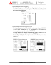
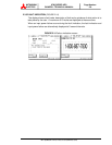
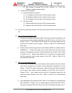
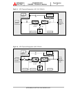
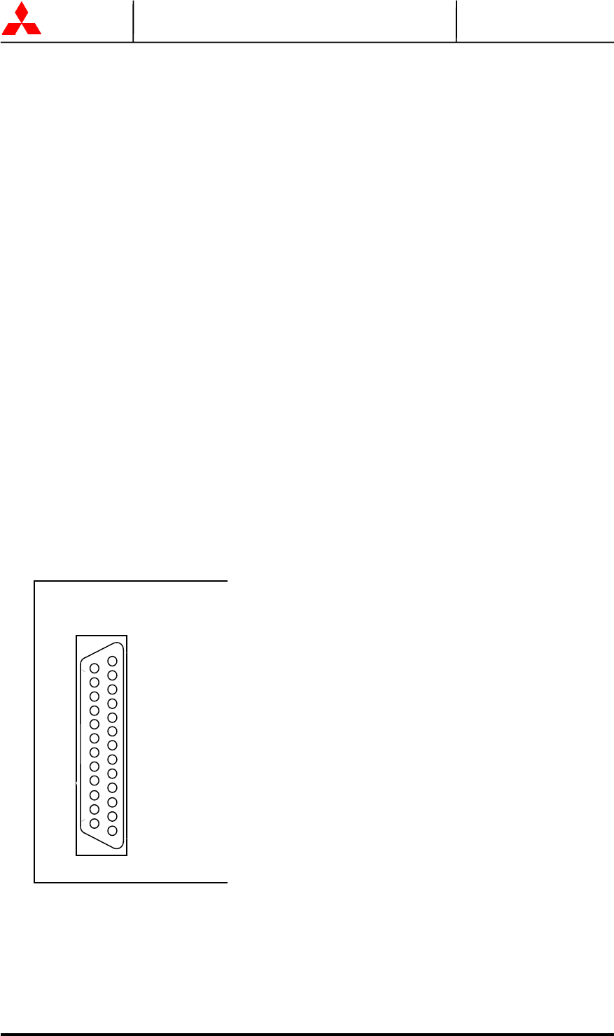
2.5 External communication connector
This is a RS232C port for “DiamondLink”. Layout of connector is shown in Figure 2.18.
FIGURE 2.18 External communication connector
Pin 2. TXD : Transmit data
Pin 3. RXD : Receive data
Pin 7. GND : Signal ground
Pin 9. 5VS : DC5V supply
Pin 10. GND : Ground
Pin 11. 5VS : DC5V supply
1
2
3
4
5
6
7
8
9
10
11
12
13
14
15
16
17
18
19
20
21
22
23
24
25
CN45
D-SUB 25Pin
PCB DPAU-ÿÿ