


MITSUBISHI
ELECTRIC
9700 SERIES UPS
OWNERS / TECHNICAL MANUAL
Page Number:
3
-2
MITSUBISHI ELECTRIC 9700 SERIES UPS
D) External Battery Supply
Please refer to the following when installing batteries:
1. The customer shall make reference to the battery manufacturer's installation
manual for battery installation and maintenance instructions.
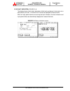
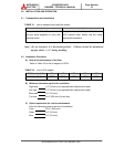
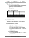
2. The maximum permitted fault current from the remote battery supply and the
DC voltage rating of the battery supply over-current protective device are
shown in Table 3.3.
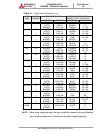
TABLE 3.3 Maximum Permitted Fault Current
UPS CAPACITY
(kVA)
DC VOLTAGE
RATING (V)
MAXIMUM PERMITTED
FAULT CURRENT (A)
100 360 35000
150 360 25000
225 360 25000
300 360 25000
375 360 25000
3.3 Procedure for Cable Connections
A) Required metric tools – 19mm wrench, 19mm socket.
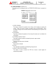
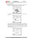
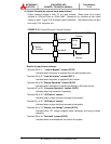
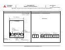
B) Confirm the capacity of the UPS being installed. Identify the input/output power
terminal blocks as shown in the appropriate Figure 3.1 through Figures 3.2-a~h.
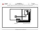
C) Connect the internal control wire and power wire.
i) Control wire Inter-connect
a) AC input cabinet (300, 375kVA only)
(1) CB1-UVR to terminal 45, 46 in bypass cabinet section.
(2) CB1 Alarm to terminal 43, 44 in bypass cabinet section.
(3) CB1 Auxiliary connect to terminal 41, 42 in bypass cabinet section.
(4) Input transformer Over-temperature to terminal 52, 54 in bypass cabinet
section.
(5) Control power A, B, C phases (Terminal block) to A00, B00, C00 in
UPS converter section.
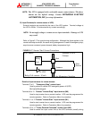
b) DC breaker cabinet or battery cabinet
(1) CB2-UVR to terminal 59, 60 (300, 375kVA) / 5, 6 (100, 150, 225kVA) in
bypass cabinet section.
(2) CB2 Alarm to terminal 57, 58 (300, 375kVA) / 1, 2 (100, 150, 225kVA)
in bypass cabinet section.