1514
E
N
G
L
I
S
H
TO INSTALL SAW CHAIN:
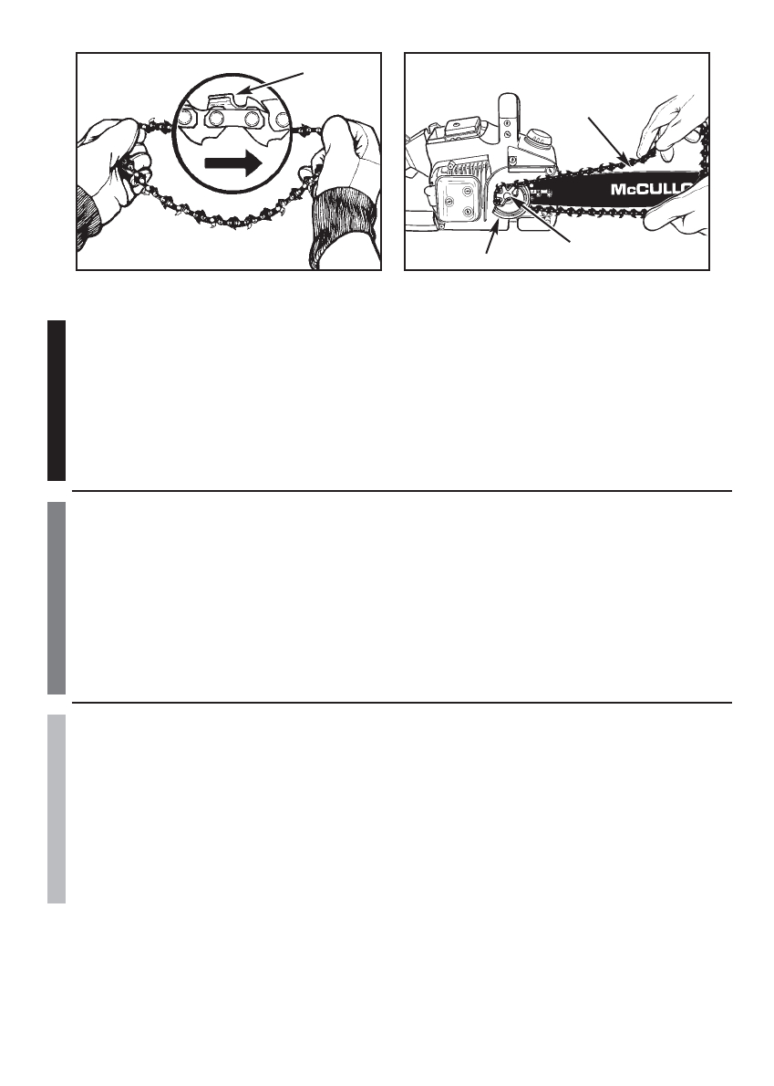
1.Spread chain out in a loop with cutting edges (A) pointing CLOCKWISE around loop (Figure 3-3F).
2.Slip the chain around the sprocket (B) behind the clutch (C). Make sure the links fit between the sprocket
teeth (Figure 3-3G).
3.Guide the drive links into the groove (D) and around the end of the bar (Figure 3-3G).
NOTE: The saw chain may droop slightly on the lower part of bar. This is normal.
4. Install the clutch cover and tighten the 2 screws. Make sure the chain does not slip off of the bar. Install
the 2 nuts hand tight and follow tension adjustment instructions in Section 3-4.
NOTE: The guide bar retaining nuts are installed only hand tight at this point because saw chain adjustment
is required. Follow instructions in Section 3-4, Saw Chain Tension Adjustment.
F
R
A
N
C
A
I
S
INSTALLATION DE LA CHAINE:
1.Ecarter la chaîne en forme de cercle avec la face (A) tranchante VERS L’AVANT sur le dessus du guide
(Figure 3-3F).
2.Faire passer la chaîne autour du pignon (B), derrière l’embrayage (C). S’assurer que les maillons s’enga-
gent entre les «dents» du pignon (Figure 3-3G).
3.Engager les maillons d’entrainement dans la rainure (D) du guide-chaîne (Figure 3-3G).
REMARQUE : La chaîne de la tronçonneuse risque de pendre légèrement sur la partie inférieure du guide-
chaîne. Ceci est normal.
4.Placer le carter d’embrayage et serrer les 2 vis. S’assurer que la chaîne ne glisse pas hors du guide-
chaîne. Serrer à la main les 2 écrous et suivre les instructions de la Section 3-4.
REMARQUE : Les écrous du guide-chaine sont serrés à la main car la chaîne devra être ajustée. Suivre les
instructions de la Section 3-4, Réglage de la Tension de la Chaîne.
E
S
P
A
Ñ
O
L
PARA INSTALAR LA SIERRA DE LA CADENA:
1.Extienda la cadena en forma de lazo con el filo de cortado (A) apuntando en DIRECCION DE LAS
MANECILLAS DEL RELOJ a lo largo del lazo (Figura 3-3F).
2.Deslice la cadena alrededor de la rueda dentada (B) atrás del embrague (C). Asegúrese que los
eslabones se ajusten dentro de los dientes de la rueda dentada (Figura 3-3G).
3.Guíe los eslabones dentro de la ranura (D) y alrededor del final de la barra (Figura 3-3G).
NOTA: La cadena de la sierra puede caer un poco en la parte baja de la barra. Esto es normal.
4.Instale la cubierta del embrague y apriete los 2 tornillos. Asegúrese que la cadena no se salga de la barra.
Instale las 2 tuercas con la mano y siga las instrucciones para el ajúste de tensión en la Sección 3-4.
NOTA: Las tuercas de la barra guía son instaladas con la presión de la mano solamente a este punto, porque
el ajúste de la cadena de la sierra es requerido. Siga las instrucciones en la Sección 3-4, Ajustes de la Tensión
de la Cadena de la Sierra.
3-3A
3-3B
3-3C
3-3D
3-3E
A
B
C
D
E
F
G
E
N
G
L
I
S
H
TO INSTALL GUIDE BAR:
CAUTION
To ensure the bar and chain receive oil, ONLY USE THE ORIGINALSTYLE BAR with the oil passage hole (A)
as illustrated above (Figure 3-3A).
1.Make sure the CHAIN BRAKE
®
lever is pulled back into the DISENGAGED position (Figure 3-3B)
2.Remove the 2 bar retaining nuts (B). Loosen the 2 screws at the rear of the clutch cover (C). Remove the
cover (Figure 3-3C).
3.Using a screwdriver, run the adjustment screw (D) COUNTERCLOCKWISE until the TANG (E) (projecting
prong) is to the end of its travel toward the clutch drum and sprocket (Figure 3-3D).
4.Place the slotted end of the guide bar over the 2 bar bolts (F). Position the bar so that the adjustment
TANG fits into the lower hole (G) on the guide bar (Figure 3-3E).
F
R
A
N
C
A
I
S
INSTALLATION DU GUIDE-CHAINE:
ATTENTION
Pour s’assurer que la chaîne et guide-chaîne soient huilés, UTILISER EXCLUSIVEMENT LE TYPE DE
GUIDE-CHAINE D ORIGINE ayant un orifice pour huile (A) comme illustré ci-dessus (Figure 3-3A).
1.Assurez-vous que le levier du CHAIN BRAKE
®
n’est PAS ENGAGE (Figure 3-3B).
2.Enlever les 2 écrous de fixation (B) du guide-chaîne. Desserrer les 2 vis arrière du carter d’embrayage (C)
et enlever le carter d’embrayage (Figure 3-3C).
3.A l’aide d’un tournevis, tourner la vis de réglage (D) VERS LA GAUCHE jusqu’à ce que la vis de tension
«LE TENON» (E) ne puisse plus avancer vers le tambour d’embrayage et le pignon (Figure 3-3D).
4. Positionner le guide-chaine sur les 2 goujons (F) de manière à ce que LE TENON (la vis de tension) puisse
pénétrer dans le trou (G) en bas du guide-chaîne (Figure 3-3E).
E
S
P
A
Ñ
O
L
PARA INSTALAR LA BARRA GUIA:
PRECAUTION
Para a
segurar que la cadena y la barra reciben aceite, USE UNICAMENTE ELESTILO ORIGINAL DE BARRA
con el hoyo de paso del aceite (A) como se ilustra arriba (Figura 3-3A).
1.Asegúrese que la manija del CHAIN BRAKE
®
sea jalada hacia atrás a la posición de DESENGANCHE
(Figura 3-3B).
2.Remueva las 2 tuercas (B) que retienen la barra. Afloje los 2 tornillos en la parte posterior de la cubierta
del embrague (C). Retire la cubierta (Figura 3-3C).
3.Usando un desarmador, corra el tornillo de ajúste (D) en DIRECCION CONTRARIA DE LAS MANECIL-
LAS DEL RELOJ hasta que la (E) ESPIGA (punta de proyección) se encuentre al final de su recorrido
hacia el tambor del embrague y el piñon (Figura 3-3D).
4.Deslice el extremo de la barra guía sobre los dos tornillos (F) de la barra. Ponga la barra de manera que
la ESPIGA de
ajúste se ajuste dentro del orificio (G) interior de la barra guía (Figura 3-3E).
3-3F
3-3G
A
B
C
D


