


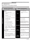

2 Maintenance
28
Copper-fin II/IIE Boiler, Water Heater and Pool Service Manual
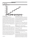
Adjusting combustion air pressure
The following is a recommended method for setting the
combustion air pressure. The following pressure settings are
for installations up to 4000 feet altitude. Contact the factory for
high altitude air pressure settings.
Upon removal of the upper front doors, locate the capped tee
in the pressure tubing that connects between the inner top and
the gas valves. Remove this cap and connect a hose from the tee
to a manometer.
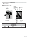
For 399,999 - 750,000 Btu/hr models (reference FIG. 2-2)
1. The combustion air chamber pressure for these models is
typically 1.2 - 1.3 inches water column when the fan is at
high speed.
2. If adjustment is necessary, slightly loosen the nuts
connecting the fan to the inner top.
3. Adjust the air shutter located underneath the fan assembly
to obtain the desired chamber pressure. Slide the shutter
inward to decrease the chamber pressure or outward to
increase the chamber pressure.
For 990,000 - 2,070,000 Btu/hr models (reference
FIG. 2-3)
1. The combustion air chamber pressure for these models is
typically 1.2 - 1.3 inches water column when the fan is at
high speed.
2. If adjustment is necessary, slightly loosen the nut
located on the air shutter arm.
3. Adjust the air shutter arm to obtain the desired chamber
pressure. Slide the arm inward to decrease the chamber
pressure or outward to increase the chamber pressure.
All models
4. Once the adjustment procedure is complete, tighten all
connections, disconnect the manometer, and replace the
cap at the tee.
5. Check all connections and test fire the unit.
6. Replace all panels.
Checking manifold gas pressure
The gas regulator on the combination gas valve is adjustable to
supply the proper manifold pressure for normal operation. The
gas valves are factory pre-set and should not need adjusting in
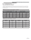
most cases. Gas manifold pressures are listed in Table 2B.
Gas manifold pressures may be checked with the use of a
manometer. Follow the steps in the Checking Combustion Air
Pressure Section prior to checking the manifold pressures.
Checking manifold gas pressure
1. Turn the appliance power switch to the “OFF” position.
2. Remove the upper outer access panels.
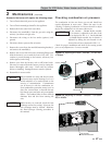
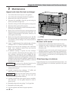
3. Remove the 1/8" hex plug from the downstream side of
the gas valve (see FIG. 2-4). Install a fitting in the tap
and connect a hose from the tap to a manometer.
4. Connect a hose from the tee used to measure the
combustion air pressure to the other side of the
manometer.
5. Turn the appliance power switch to the “ON” position.
6. With the unit at high fire, check and record the
manifold pressure of the valve. The manifold pressure
will be the sum of the two pressure readings (reference
Table 2B).
7. Repeat this process with each gas valve.
ƽ WARNING
Overfire and underfire hazards!
Possible fire, explosion, overheating,
and component failure. Do not attempt
to adjust firing rate of the appliance.
The firing rate must be adjusted only by
factory trained personnel.
If you must adjust the gas valve regulator pressure,
follow the steps below:
1. Remove the cap covering the manifold pressure
adjustment screw (see FIG. 2-4). Note: Once the cap
is removed, the pressure shown on the manometer will
change and the unit may turn off.
2. Make a slight adjustment to the manifold pressure
adjustment screw. Turning the screw clockwise
increases manifold pressure and counterclockwise
decreases manifold pressure.
3. Replace the cap and check the manifold pressure.
Note: Allow the unit to re-light if necessary.
4. Repeat the steps above to match the manifold pressures
from Table 2B.
5. Once the adjustment procedure is complete, turn off
the appliance, disconnect the manometer, replace and
tighten all connections, and replace all panels.
6. Turn on the appliance and test fire the unit.
7. Repeat this process with each gas valve.