


1 Service
16
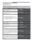
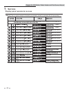
B3: SH Maximum set point
The SH maximum set point sets the maximum water
temperature set point that can be used for space heating. The
user or installer will not be able to program the control with a
higher SH set point. This parameter can only be changed by the
installer by accessing parameter B3. The temperature range of
this parameter is 32°F (0°C) to 230°F (110°C) (space heating)
or 32°F (0°C) to 105°F (40°C) (pool heater). The default value
is 220°F (104°C) (space heating) or 105°F (55°C) (pool heater).
B4: SH Offset
The SH offset sets how many degrees above set point the
temperature has to go before the unit will shut off. This
parameter can only be changed by the installer by accessing
parameter B4. The temperature range of this parameter is 0°F
(0°C) to 54°F (30°C). The default value is 10°F (5°C) (boiler) or
2°F (1°C) (pool heater).
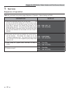
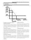
B5: SH Differential
The SH differential sets how many degrees below the turn off
temperature the temperature has to go before the unit will
turn on. This parameter can only be changed by the installer
by accessing parameter B5. The temperature range of this
parameter is 0°F (0°C) to 54°F (30°C). The default value is 20°F
(11°C) (boiler) or 4°F (2°C) (pool heater).
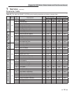
B6: Manual reset high limit
The SMART SYSTEM control includes an integrated manual
reset high limit (MRHL) feature, based on the outlet temperature.
The set point for the MRHL is adjusted using parameter B6.
The temperature range of this parameter is 32°F (0°C) to 210°F
(99°C) for water heaters and pool heaters, or 240°F (115°C) for
boilers. The default value is 210°F (99°C) for boilers and water
heaters, or 200°F (93°C) for pool heaters.
B7: Auto reset high limit
The SMART SYSTEM control also includes an integrated auto
reset high limit (ARHL) feature, based on outlet temperature.
The ARHL set point is fixed at 205°F (96°C) for water heaters,
and 185°F (85°C) for pool heaters. For boilers, the temperature
range of this parameter is 32°F (0°C) to 235°F (113°C). The
default value is 200°F (93°C).
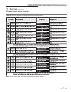
C: Data logging
C1: Hours running SH
The hours running SH parameter shows the total number of
hours the unit has been in the SH firing mode. This parameter
can be viewed by the user and the installer by accessing
parameter C1.
C2: Hours running DHW
The hours running DHW parameter shows the total number
of hours the unit has been in the DHW firing mode. This
parameter can be viewed by the user and the installer by
accessing parameter C2.
C3: Burner cycles
The burner cycles parameter shows the total number of times
the unit has attempted to fire. This parameter can be viewed by
the user and the installer by accessing parameter C3.
C4: Show last 10 lockouts
The control will log the 10 most current lockouts with the date
and time the lockout occurred. This parameter can be viewed
by the user and the installer by accessing parameter C4.
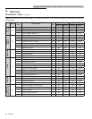
D: Functions
D1: Reset last 10 lockouts
The reset last 10 lockouts parameter allows the lockout counter
to be reset to 0. This parameter can only be cleared by the
installer by accessing parameter D1. Once accessed, press the
RESET key to clear the counter.
D2: Service mode delay
By pressing the PREVIOUS and NEXT keys on the front of
the display for five (5) seconds, the control will be placed
in Service Mode. This will override all other heat demands.
The Service Mode allows the installer to set the unit to either
maximum firing rate or minimum firing rate for the purpose
of combustion analysis. The delay sets the length of time the
unit will stay in the Service Mode if no keys have been pressed
before going back to its original state. This parameter can only
be changed by the installer by accessing parameter D2. The
time range of this parameter is 0 to 40 minutes. The default
value is 20 minutes.
D3: Display timeout
Whenever a button on the display is pushed, the backlight on
the LCD is turned on, and a delay timer is reset. When this
timer expires, the backlight turns off, and the display returns
to the first Status Screen. The value of this timer can be
adjusted using parameter D3. The range of this timer is 0 to
255 seconds. Setting this parameter to 0 disables the backlight.
The default value is 60 seconds.
D4: Bypass valve time
In low temperature systems, a 3-way bypass valve can be
installed between the outlet and the inlet of the heater (see
Installation and Operation Manual). The SMART SYSTEM
control can be set to automatically control this valve to maintain
the inlet temperature above the condensing temperature.
Different valves require different amounts of time to open
and close completely. The SMART SYSTEM controls need to
know how long this takes in order to control the bypass valve
properly. This time can be adjusted using parameter D4. The
range of this parameter is 0 to 255 seconds. The default value
is 20 seconds.
Copper-fin II/IIE Boiler, Water Heater and Pool Service Manual