


1 Service (continued)
21
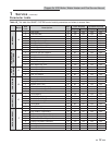
I: Cascade
I1: Cascade address
The boiler designated as the Leader needs to be programmed
with address 0. All the Member boilers require addresses from
1 to 7, and the addresses must be different for each Member.
The addresses can be in any order, regardless of the order in
which the units are wired together. This parameter is adjustable
by the installer by accessing parameter I1. The outdoor air (if
used), system supply sensor, and system return sensor must be
connected to the Leader boiler. The default address is 1.
I2: Max. outlet set point
When the system supply sensor is connected, or the system
supply temperature is provided through ModBus, this parameter
determines the set point used by the individual boilers in a
Cascade. When a boiler is commanded to fire by the Leader
boiler, it will attempt to achieve this temperature at its outlet.
The Leader boiler will limit the modulation of the last boiler to
fire in order to hold the temperature at the system supply sensor
to the user set point. If any of the boiler outlet temperatures
reach the max. cascade set point, the boiler will then modulate
down on its own in order to keep its outlet temperature
within the max. cascade set point. Therefore, this parameter
can be used to limit the outlet temperatures of all the boilers
in a Cascade. Note that this parameter does not apply when
the boiler is heating an indirect DHW tank. This parameter
is adjustable by the installer by accessing parameter I2. The
temperature range for this parameter is 32°F (0°C) - 261°F
(127°C). The default max. cascade set point is 185°F (85°C).
I3: Cascade offset (boilers only)
This parameter determines how much the temperature must
go above set point before the lead boiler will turn off. This
parameter can be adjusted by the installer by accessing parameter
I3. The temperature range for this parameter is 0°F (0°C) - 54°F
(30°C). The default value is 9.9°F (5°C).
I4: Cascade differential (boilers only)
This parameter determines how much the temperature must
go below the turn off temperature (Set point + Offset) before
the lead boiler turns on. This parameter can be adjusted by the
installer by accessing parameter I4. The temperature range for
this parameter is 0°F (0°C) - 54°F (30°C).The default value is
19.8°F (11°C).
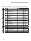
J: Building Management System (BMS)
J1: BMS type
When the unit or cascade is controlled by the 0-10V BMS input,
the voltage signal can control either the firing rate (power) or
the set point. This parameter may be adjusted by the installer by
accessing parameter J1. The default value is Power.
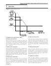
J2: Voltage at minimum
This setting determines the voltage at which the external
signal begins to increase either the modulation or the set
point. Below this voltage, the modulation or set point will
be at their minimum values. This parameter can be adjusted
by the installer by accessing parameter J2. The range for this
parameter is 0V - (J3 - 0.1V). The default value is 2V.
J3: Voltage at maximum
This setting determines the voltage at which the external signal
forces either the modulation or the set point to their maximum
value. This parameter, along with the previous parameter,
determines how much the modulation or set point changes as
the BMS input voltage changes. The modulation or set point
will change in proportion to the change in voltage between the
minimum and maximum voltage settings. This parameter may
be adjusted by the installer by accessing parameter J3. The
range for this parameter is (J2 + 0.1V) - 10V. The default setting
is 10V.
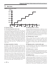
J4: Power at low voltage
This setting determines the modulation of the unit or cascade
when the BMS input voltage is at or below the Voltage at
Minimum setting. This parameter is active only when the
BMS type is set to Power. This parameter may be adjusted
by the installer by accessing parameter J4. The range for this
parameter is 0 - J5. The default value is 20%.
J5: Power at high voltage
This setting determines the modulation of the unit or cascade
when the BMS input voltage is at or above the Voltage at
Maximum setting. This parameter is only active when the
BMS type is set to Power. This parameter can be adjusted
by the installer by accessing parameter J5. The range for this
parameter is J4 - 100%. The default value is 100%.
J6: Set point at low voltage
This setting determines the set point used by the unit or cascade
when the BMS voltage is at or below the Voltage at Minimum
setting. This parameter is only active when the BMS type is set
to Set Point. This parameter can be adjusted by the installer
by accessing parameter J6. The temperature range for this
parameter is 32°F (0°C) - 230°F (110°C) (boilers), 32°F (0°C)
to 190°F (87°C) (water heaters), or 32°F (0°C) to 105°F (40°C)
(pool heaters). The default value is 70°F (21°C).
Copper-fin II/IIE Boiler, Water Heater and Pool Service Manual