


27
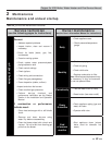
2 Maintenance (continued)
Copper-fin II/IIE Boiler, Water Heater and Pool Service Manual
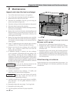
Access to the burner will require the following steps:
1. Turn off main electrical power to the appliance.
2. Turn off main manual gas shutoff to the appliance.
3. Remove the lower outer front access door.
4. Disconnect the manifold(s) from the gas train using the
union(s) just below each gas valve.
5. Disconnect the wiring to the hot surface igniter(s) and
ground.
6. Disconnect burner pressure line at burner.
7. Remove the screws from the manifold mounting bracket(s)
and remove the manifold(s).
8. Remove the screws from the burner mounting flanges and
slide the burner(s) out toward the front of the unit. Use
caution to prevent damage to the burners, refractory, hot
surface igniter, and wiring.
9. Remove soot from the burners with a stiff bristle brush.
Dirt may be removed from the burner ports by rinsing the
burner thoroughly with water. Drain and dry burners
before re-installing. Damaged burners must be replaced.
10. Reassemble in reverse order.
When installed in a dusty and dirty location,
the burners may require cleaning on a 3 to 6
month schedule or as needed, based on the
severity of contamination. Contaminants
can be drawn in with the combustion air.
Non-combustible particulate matter such as
dust, dirt, concrete dust, or drywall dust can
bloc burner ports and cause non-warrantable
failure. The standard inlet air filter will help
eliminate dust and dirt from entering the
unit.
NOTICE
While burners are removed, check the heat
exchanger surface for sooting. If present, the
heat exchanger must be cleaned. Reference
the Heat Exchanger Cleaning procedures in
this manual.
NOTICE
Checking combustion air pressure
The combustion air fans are factory pre-set and should not
require adjustment in most cases. Follow the steps in the
Checking / Adjusting Combustion Air Pressure Section to adjust
the fan if a continuous Low Air status code occurs.
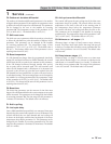
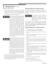
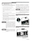
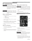
On the 399,999 - 750,000 Btu/hr models,
the air shutter is adjusted to the side of the
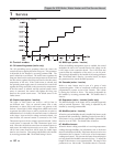
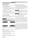
fan as depicted in FIG. 2-2. On the 990,000
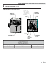
- 2,070,000 Btu/hr models, the air shutter is
adjusted by sliding the arm located on the
front of the air box as depicted in FIG. 2-3.
NOTICE
Check for proper installation and draft in the venting system
prior to any adjustments. Correct as needed.
AIR SHUTTER
LESS AIR
MORE AIR
Figure 2-2_Adjusting air shutter - 399,999 - 750,000 Btu/
hr Models
AIR SHUTTER
ADJUSTING BRACKET
LESS AIR
MORE AIR
Figure 2-3_Adjusting air shutter - 990,000 - 2,070,000
Btu/hr Models