


H: Control modes
H1: SH controlling sensor (boiler only)
The SH controlling sensor parameter selects the sensor the
control will use to regulate the boiler firing rate. This parameter
is adjustable by the installer by accessing parameter H1. The
sensor selections are as follows: The outlet sensor regulates the
firing rate based on the outlet water temperature of the unit and
the inlet sensor regulates the firing rate based on the inlet water
temperature of the unit. If the outlet sensor is selected, and
the optional system supply sensor is connected, the control will
regulate the firing rate based on the system sensor temperature.
If the inlet sensor is selected, and the optional system return
sensor is connected, the control will regulate the firing rate
based on the system return sensor. The default sensor is the
Outlet Sensor.
H2: Enable input (active / inactive)
The boiler or water heater can receive a call for heat in
two different ways. First, an external contact (like a tank
thermostat) or sensor (like a tank sensor) can generate a call
for heat. Second, the 0-10Vdc voltage from a BMS can be used
to generate the call for heat, as well as provide the set point or
modulation level. On boilers, the external contact is connected
to the Stage 1 input on the low voltage connection board. On
water heaters, the external contact is connected to the Tank
Thermostat input on the low voltage connection board. When
a tank sensor is connected, the Tank Thermostat input is not
used. When the call for heat comes from an external contact or
tank sensor, the enable input must be set to active. When the
call for heat comes from the 0-10Vdc input, the enable input
must be set to inactive. This setting is adjustable by the installer
by accessing parameter H2. The default setting is Active.
H3: BMS input (active / inactive)
When the building management input is enabled, the control
modulates the unit or the cascade based on the voltage on the
0-10V input on the connection board. The 0-10V input may
control either the modulation of the unit(s), or the set point.
This setting is adjustable by the installer by accessing parameter
H3. The default value is Inactive. See menu Section J to adjust
the parameters that control the BMS operation.
H4: Cascade (active / inactive)
Boilers or water heaters may be part of a group of units
sequenced together. When so connected, each heater must be
programmed to operate as part of the Cascade. This is done
by setting the Cascade to Active. This setting is adjustable by
the installer by accessing parameter H4. The default value is
Inactive.
H5: Sequencer (active / inactive) (boiler only)
The individual stages in the heater can be controlled separately
with an external sequencer. This setting is adjustable by the
installer by accessing parameter H5.
H6: ModBus (active / inactive)
When the optional ModBus board is installed, the heater can be
monitored and controlled by a Building Control System (BCS).
If the heater is to be controlled through ModBus, parameter H6
must be set to ACTIVE. The default value is Inactive.
H7: ModBus timeout
When the heater is being controlled or is receiving temperature
readings through ModBus, the information sent to the heater
must be refreshed periodically. If the heater does not receive new
information after a timeout, it will revert to local temperature
readings and control. This prevents the heater from running for
too long should the ModBus connection be lost. To adjust the
length of this timeout, access parameter H7. The range of this
parameter is 0 to 120 seconds. The default value is 10 seconds.
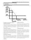
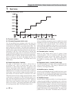
Figure 1-2_Ramp Delay Interval
1 Service
Copper-fin II/IIE Boiler, Water Heater and Pool Service Manual
20