


22
Section 3: Adjustments
WC1503 Wood Chipper 328-085M
Table of Contents
12/15/15
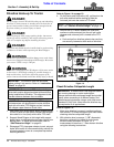
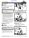
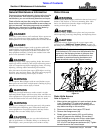
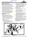
2. Place 1/32" to 1/16" shim between knife edge and
knife ledger. Do not exceed 1/16" gap.
3. Adjust knife ledger against the shim. Hold ledger in
this position to tighten bolts (#3) in step 4 below.
4. Tighten GR8 Ledger bolts (#3) to 35-40 ft-lbs. See
“Additional Torque Values” on page 34 for more
information.
5. Continue with step 4.c. under “Check Knife Ledger
Clearance” on this page.
View of Rotor Knife (#4) With Feed Chute Removed
Figure 3-6
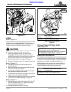
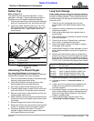
V-Belt Take-up
Refer to Figure 3-7
The V-belts transmit power to the rotor knives and should
be adjusted if they are slipping under normal load. If
V-belts are slipping under normal load, then make
adjustments as follows.
1. Make certain gear selector is in park and park brake
is set. Disengage PTO, shut tractor engine off,
remove switch key and wait for all moving parts to
stop completely before working on this.
2. Disconnect driveline from tractor PTO shaft.
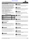
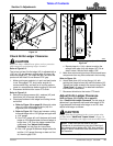
3. Remove the three hex flange screws (#7) and belt
guard (#6).
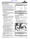
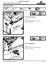
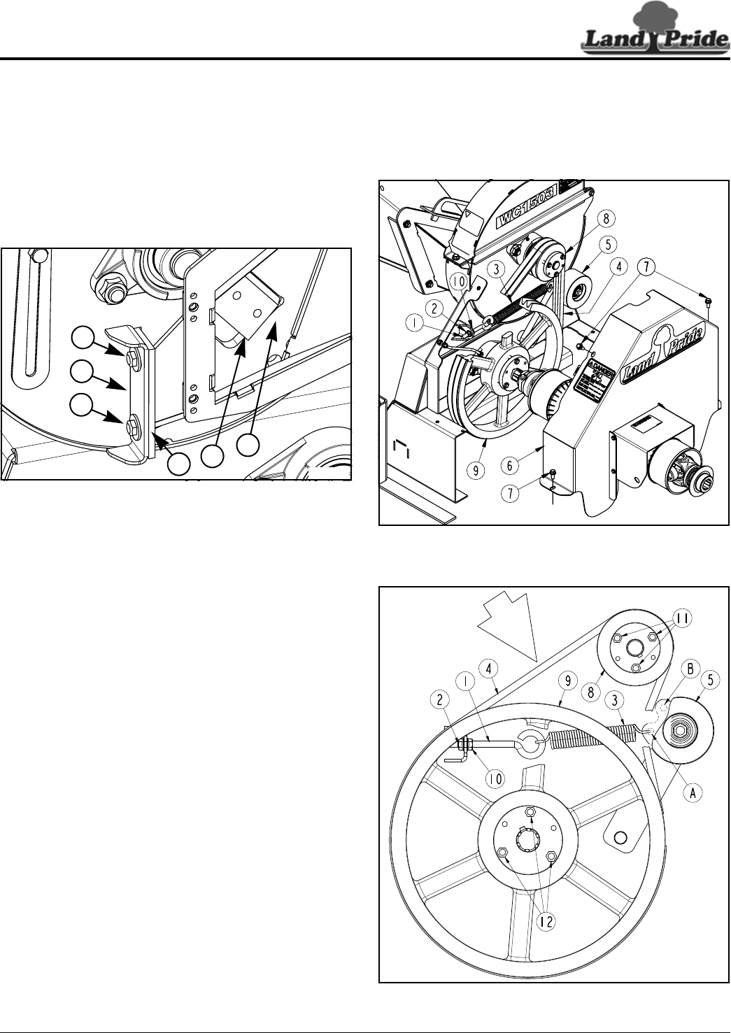
Refer to Figure 3-8
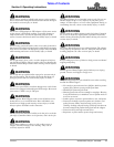
4. Push on the belt at mid-point between the two
pulleys. The belt should deflect 1" with 10 lbs. of
force. If belt needs tightened, go to step 5 below.
5. Tighten belt by loosening hex flange nut (#10) and
screwing hex flange nut (#2) clockwise to pull on
take-up spring (#3) and take-up pulley (#5).
6. If eyebolt (#1) runs out of threads before V-belts (#4)
are properly tensioned, then loosen eye bolt until
take-up spring (#3) can be moved from hole “A” to
hole “B”.
7. With take-up spring in hole “B” retighten eye bolt (#1)
with hex flange nut (#2) until V-belts are properly
tensioned.
8. Tighten hex flange nut (#10).
35265
5
2
3
3
4
1
Refer to Figure 3-7
9. Replace belt guard (#6) with existing 5/16"-18 x 3/4"
GR5 hex flange screws (#7). Tighten hex flange
screws to the correct torque.
10. Reconnect driveline to tractor PTO shaft.
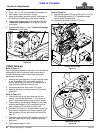
Remove Pulley Guard
Figure 3-7
Adjust Belt Take-Up
Figure 3-8
35260
35261