


20
Section 3: Adjustments
WC1503 Wood Chipper 328-085M
Table of Contents
12/15/15
Section 3: Adjustments
Adjustment Safety
!
DANGER
Always disengage PTO, engage parking brake, shut tractor
engine off, remove switch key, and wait for all moving parts to
come to a complete stop before making any adjustments.
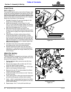
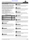
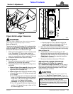
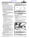
Skid Extension Height
Refer to Figure 3-1:
1. Make sure PTO is disengaged, gear selector is in
park, and park brake is set. Adjust tractor
3-Point up or down until driveline is close to level.
2. Place support blocks under the chipper but not under
the skid extensions (#1) to keep the chipper from
drifting down while adjusting the skid extensions.
3. Lower Wood Chipper onto the support blocks, shut
tractor engine off, and remove switch key.
4. Remove hex flange lock nuts (#3) and hex head cap
screws (#2).
5. Lower skid extensions (#1) to the ground and reinsert
1/2"-13 GR5 cap screws (#2). Secure cap screws
with existing hex flange lock nuts (#3). Tighten lock
nuts to the correct torque.
6. Raise tractor 3-Point up and remove support blocks.
Lower unit until resting on its skid extensions.
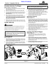
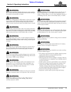
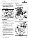
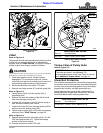
Discharge Chute Angle
Refer to Figure 3-2:
!
WARNING
Adjust discharge chute to direct material away from operator,
people, animals, equipment, and buildings. The Wood Chipper
can throw objects and cause an injury.
1. Push down on rotation chute lock lever (#2) and hold.
2. Rotate discharge chute (#1) in small increments until
desired angle of discharge is achieved.
3. Release rotation chute lock lever (#2). Make sure
lever has locked into position and chute cannot
rotate.
IMPORTANT: The Wood Chipper operates best and
driveline u-joint life is increased if skid extensions
are set at a height that will allow the unit to rest on
the skid extension with driveline operating level or as
close to level as possible.
NOTE: This effects loading height for wood.
NOTE: Chute is limited to 270
o
rotation so as not to
get into loading area.
Adjust Skid Extension Height
Figure 3-1
Adjust Discharge Chute Angle
Figure 3-2
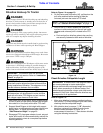
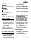
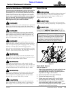
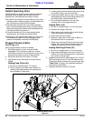
Deflector Chute Angle
Refer to Figure 3-3:
1. Loosen hand knobs (#2) and rotate deflector
chute (#1) up or down to the desired angle.
2. Retighten hand knobs (#2).
Adjust Deflector Chute Angle
Figure 3-3
35256
35254
35255