


11
Section 1: Assembly & Set-Up
WC1503 Wood Chipper 328-085M
Table of Contents
12/15/15
Section 1: Assembly & Set-Up
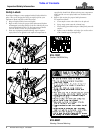
Tractor Requirements
Tractor horsepower rating is 12 to 30 hp. with a minimum
of 25 hp when operating at maximum capacity. Tractors
outside the horsepower range must not be used.
The rear power take-off (PTO) speed must be 540 RPM
maximum and have a 1 3/8”-6 spline PTO shaft.
A 3-Point Category I hitch is required. The lower 3-Point
arms must be stabilized to prevent side-to-side
movement. Most tractors have sway blocks or adjustable
chains for this purpose.
!
WARNING
Ballast weights may be required to maintain steering control.
Refer to your tractor’s operator’s manual to determine proper
ballast requirements.
Dealer Preparations
Make sure that the intended tractor conforms to the
“Tractor Requirements” stated above. Read and
understand the Operator’s Manual for this Wood Chipper.
An understanding of how it works will aid in its assembly
and setup.
Go through the Assembly Checklist before assembling
the Wood Chipper. Speed up your assembly task and
make the job safer by having all needed parts and
equipment readily at hand.
Torque Requirements
Refer to “Torque Values Chart” on page 34 to
determine correct torque values for common bolts.
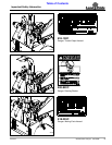
Assembly Checklist
✔ Check Ref.
Make sure miscellaneous assembly tools are on hand:
Assortment of wrenches & sockets.
Have a minimum of two people available during assembly.
Check to see if ballast weights are needed.
See specifications for weight of Wood Chipper.
Page 30
Make sure all major components, driveline, and
loose parts are shipped with the machine. Refer
to section on “Assembly and Set-Up”.
Pages
11-15
Make sure all fasteners & pins are installed in
the correct location.
Refer to the Parts Manual if unsure.
Parts Manual
328-085P
Make sure all bolts are tight and cotter pins are
spread. Refer to “Torque Values Chart”
Page 34
Make sure all grease fittings are in place &
lubricated. Refer to “Lubrication Points”
Page 28
Make sure drive belts are aligned & tensioned.
Refer to “V-Belt Take-up”.
Page 22
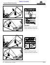
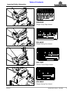
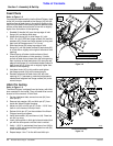
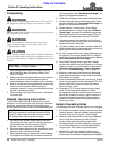
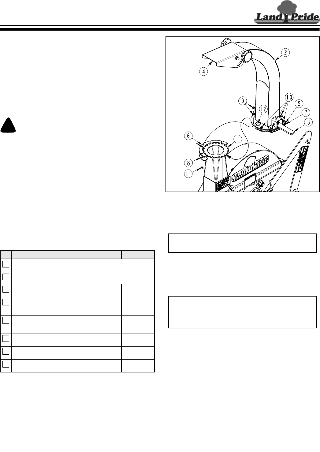
Discharge Chute Assembly
Figure 1-1
Discharge Chute
Refer to Figure 1-1:
1. Loosen the four rear bolts (#10) by two or three turns.
Do not remove bolts or nuts securing bolts.
2. Remove the front four bolts (#9), half-clamp
plate (#8), and half-spacer plate (#6) from discharge
spout (#2). Keep hardware for reuse.
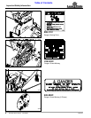
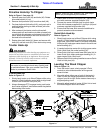
3. Make sure bottom half-clamp plate (#7) is positioned
against underside of notched plate (#1). Being
careful not to damage plastic bearing (#12), slide
front of discharge chute (#2) onto notched plate (#1)
until discharge chute is centered over the notched
plate.
4. Place half-spacer plate (#6) on top of half-clamp
plate (#8) with bolt holes in alignment with each
other.
5. Position bottom half-clamp plate (#8) against
underside of notched plate (#1) as shown.
6. Bolt chute (#2) to half-spacer plate (#6) and half-
clamp plate (#8) with the four removed 1/4”-20 x 3/4"
GR5 cap screws (#9) and hex lock nuts (#11).
7. Draw all eight hex lock nuts (#11) up snug and then
back each one off 1/2 turn.
35251
NOTE: Half-clamp plate (#8) and half-spacer
plate (#6) are shipped bolted to discharge spout (#2).
IMPORTANT: Be careful not to damage plastic
bearing attached with adhesive to underside of
discharge chute while attaching chute to the
chipper’s notched plate.