


14
Section 2: Options, Assembly & Set-Up
RBT55120 Rear Blades 301-172M
5/21/07
Land Pride
Table of Contents
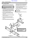
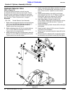
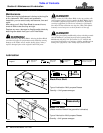
Hydraulic Selector Valve Assembly
Figure 2-6
25509
Hydraulic Selector Valve
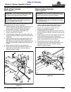
Refer to Figure 2-6:
An optional hydraulic selector valve kit may be
purchased that bolts to the front hitch frame. This kit
provides a way to operate 2 cylinders with one outlet,
thereby reducing the number of outlets at the tractor by
one. See also “Tractor Requirements” on page 7.
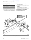
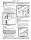
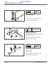
Kit Bundle
300-154A Double Selector Valve Assembly
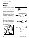
1. Attach diverter valve stand (#16) to the hitch with two
1/2"-13 x 1 3/4" GR5 hex head cap screws (#17),
spring lock washers (#10) and hex nuts (#11).
Tighten nuts to the correct torque.
2. Attach adjustment tube (#13) to the stand with one
1/2"-13 x 3/4" GR5 hex head cap screws (#15).
Tighten bolt to the correct torque.
3. Attach extension arm (#14) to adjustment tube with
two 3/8”-16 x 3/4” GR5 hex head cap screws (#12).
Tighten bolts to the correct torque.
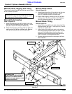
4. Attach valve base plate (#6) to extension arm (#14)
with two 1/2” flat washers (#9), lock washer (#10) and
3/8”-13 hex nut (#11). Tighten nut to the correct
torque.
5. Attach double selector valve (#4) to valve base
plate (#6) with two 3/8"-16 x 3" GR5 hex head cap
screws (#5), spring lock washers (#7) and hex
nuts (#8). Tighten nuts to the correct torque.
6. Apply teflon tape to the pipe threads of six
3/4 x 1/2MNPT elbows (#1) and screw them into the
double selector valve (#4) as shown. Tighten to
correct orientation.
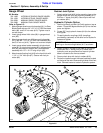
7. Attach blade offset hydraulic hoses (#18) to the right
side elbows.
8. Attach hydraulic hoses (#19) from one of the other
cylinders to the left elbows.
9. Attach tractor connected hydraulic hoses (#2) to the
top elbows.
10. Thread hydraulic adapters (#3) (couplings supplied
by customer) onto hydraulic hoses (#2) and tighten.