


12
Section 1: Assembly and Set-up
RCR2684 Rotary Cutter 312-785M
9/24/08
Land Pride
Table of Contents
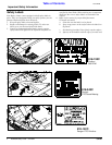
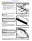
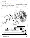
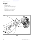
3-Point Tractor Hook-Up
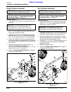
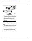
Figure 1-9
266
3
3. Engage tractor park brake, shut tractor engine off
and remove key before dismounting from tractor.
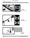
4. With tractor’s lower hitch arms aligned and
positioned in the clevises, attach the lower arms to
the clevises with hitch pins (#1) and secure with
linchpins (#3).
5. If required, start tractor and slowly raise 3-point hitch
to align center link with hitch pin hole. Shut tractor
engine off as described in step 3 once aligned.
6. Connect top center link (#4) to upper hitch with
customer supplied 1” clevis pin (#5) and hairpin
cotter (#6). If your tractor is a Category III, then a
customer supplied 1 1/4” spacer (#7) will be
required.
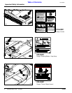
7. Ensure that the lower hitch arms are blocked to
prevent excessive side movement.
8. Return to tractor and slowly operate controls up and
down to ensure that the drawbar, tires, and other
equipment on the tractor do not contact the deck and
PTO driveline. Move or remove drawbar if it
interferes.
9. Manually adjust one of the two Lower lift arms up or
down to level the Rotary Cutter from left to right.
10. Manually adjust the center link (#4) length to level
cutter from front to rear. Additional adjustments will
be made later.
11. The lift link rods on your tractor’s 3- point hitch should
be adjusted to allow for lateral float. Please consult
you tractor’s manual for adjusting instructions.
Tractor Hook-Up
3-Point Tractor Hook-Up
!
DANGER
Tractor hook-up to equipment is dangerous and can result in
serious injury or death. Do not allow anyone to stand between
the Rotary Cutter and tractor during hook-up operations. Do
not operate the hydraulic 3-point lift controls while someone
is directly behind the tractor or near the cutter.
A 3-Point Category II or Category III hitch is required.
The lower 3-Point arms of the 3-Point hitch must be
stabilized to prevent side-to-side movement. Most
tractors have sway blocks or adjustable chains for this
purpose.
Determine your tractor’s hitch category.
• A Category II tractor will have a 1 1/8” dia. hole in the
lower hitch links and a 1” dia hole in the top link.
• A Category III tractor will have a 1 7/16” dia. hole in the
lower hitch links and a 1 5/16” dia hole in the top link.
Refer to Figure 1-9:
1. Locate cutter on a flat level surface.
2. Slowly back tractor up to theRotary Cutter while using
the tractor’s 3-point hydraulic control to position the
tractor’s lower hitch link holes (#2) in the clevis and
aligned with the hitch pins (#1).