


8
Section 1: Assembly and Set-up
RCR2684 Rotary Cutter 312-785M
9/24/08
Land Pride
Table of Contents
Section 1: Assembly and Set-up
Tractor Requirements
Tractor horsepower should be within the range noted
below. Tractors outside the horsepower range must not
be used.
Horsepower Rating. . . . . . . . . . . . . . . . . . 60-110 HP
Rear PTO Shaft Type . . . . . . . . . . . . . 1 3/8”-6 Spline
Rear PTO Speed . . . . . . . . . . . . . . . . . . . . 540 RPM
Hitch Type . . . . . . . . . . . . . . . . . . 3-Point Cat. II or III
Tractor Weight . . . . . . . . . . . . . . . . . See Note Below
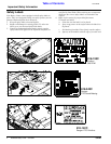
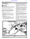
Vent Plug With Dipstick Installation
Refer to Figure 1-1:
A vent plug with dipstick is included in the bag with this
manual. Remove temporary solid plug from top of
gearbox and replace with vent plug and dipstick.
Hitch Assembly
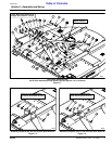
Refer to Figure 1-1 for Cat. II & Cat. III Hitches:
1. Assembly hitch straps (#4 & #5) to clevis plates with
1 1/4” SAE flat washers (#22) and 1 1/4”-12 top lock
nuts (#14).
2. Assemble hitch braces (#1) to rear strap lugs with
5/8"-11 x 1 1/2" bolts (#11), spacers (#2), 5/8” flat
washers (#19) and 5/8" lock nuts (#17).
NOTE: In order to maintain steering control, ballast
may need to be added to your tractor. To determine
whether or not to add ballast, refer to your tractor’s
operator manual.
IMPORTANT: RCR2684 Rotary Cutters are shipped
with a solid plug in the gear box to prevent loss of oil
during shipping and handling. Before operating the
cutter, replace solid plug with a vent plug.
NOTE: Do not tighten hardware until assembly
is complete. Refer to “Torque Values Chart for
Common Bolt Sizes” on page 32.
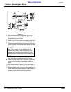
IMPORTANT:
Refer to Figure 1-1 & Figure 1-2:
Bushing (#3), bolt (#6B) & stop pin (#9) are installed
in one set of holes for Cat. II set-up (Figure 1-1) and
in another set of holes for Cat. III set-up (Figure 1-2
& Figure 1-3). Be sure you know which Category
your 3-point hitch is and that your following
instructions for your hitch Category.
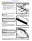
Refer to Figure 1-1 for Cat. II Hitch
And Figures 1-2 & 1-3 for Cat. III Hitch:
3. (See Important note below for Cat. III hook-up.)
Insert 1”-8 x 4 1/2” GR5 hex head bolt (#12) through
left hand hitch strap (#4), 1 1/4” OD Bushing (#3),
right hand hitch strap (#5) and 1” lock washer (#21).
Secure with 1”-8 hex nut (#13).
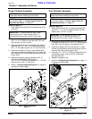
Refer to Figure 1-1 for Cat. II & Cat. III Hitches:
4. Insert 3/4”-10 x 4” GR5 hex head bolt (#6A) through
left hand hitch strap (#4), 3/4” flat washer (#20), rear
brace hinge (#7A), 1 1/4” OD x 1 1/32” lg spacer (#8),
rear brace hinge (#7B), 3/4” flat washer (#20) and
right hand hitch strap (#5). Secure with 3/4” hex
flange lock nut (#15). Draw hex flange lock
nut (#15) up snug and then back off 1/4 turn.
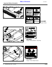
5. Insert stop pin (#9) through the two rear brace hinges
(#7A & #7B). Secure between the two braces with
cotter pins (#23). Bend cotter pins legs to prevent
them from falling out.
6. Rotate hitch straps (#4 & #5) and hitch braces (#1)
up as shown.
7. Insert 3/4”-10 x 4” GR5 hex head bolt (#6B) through
left hitch brace (#1), 3/4” flat washer (#20), left rear
brace hinge (#7A), 1 1/4” OD x 1 1/32” lg spacer (#8),
right rear brace hinge (#7B), 3/4” flat washer (#20)
and right hitch brace (#1). Secure with 3/4” hex
flange lock nut (#15). Draw hex flange lock
nut (#15) up snug and then back off 1/4 turn.
8. Tighten hex nuts (#13, #14 & #17) to the correct
torque.
Manual Storage Tube Assembly
Refer to Figure 1-1:
1. Attach manual storage tube (#25) to the cutter deck
with two 1/4”-20 GR5 hex head cap screws (#11), flat
washers (#19) and hex head nuts (#17). Tighten nuts
to the correct torque.
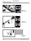
IMPORTANT: Special Cat. III Hook-Up Instructions.
Refer to Figure 1-2:
Bolt (#12) and spacer (#3) is installed in the top hole
when attaching the mower to a tractor with a quick
hitch set-up.
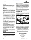
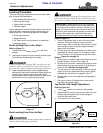
Refer to Figure 1-3:
Bolt (#12) and spacer (#3) is installed in the bottom
hole when attaching the mower to the tractor’s
3-point hitch system.