


31
Section 4: Maintenance & Lubrication
12/15/15
RCF2784 Rotary Cutters 326-364M
Table of Contents
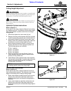
Always inspect cutting blades before each use. Make
certain they are properly installed and are in good working
condition. Replace any blade that is damaged, worn, bent,
or excessively nicked. Small nicks can be ground out.
Remove blades and sharpen or replace as follows:
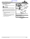
1. Place tractor gear selector in park and set brakes,
shut engine off and remove ignition key.
2. Disconnect main driveline from tractor PTO and
secure cutter deck in the up position with solid
supports before servicing underside of cutter.
3. Inspect cutting blades. Make certain they are
properly installed and are in good working condition.
Replace any blade that is damaged, worn, bent, or
excessively nicked. Small nicks can be ground out.
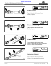
Refer to Figure 4-1:
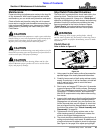
4. To remove blades from the cutter, remove access
cover (#6).
5. Rotate blade bolt (#1) until aligned with access
hole (A).
6. Unscrew locknut (#3) to remove cutting blade (#6).
Blade bolt (#1) is keyed and will not turn freely.
7. Repeat steps 5 & 6 for the other blade.
8. Both blades should be sharpened at the same angle
as the original cutting edge and must be replaced or
re-ground at the same time to maintain proper
balance in the cutting unit. The following precautions
should be taken when sharpening blades:
a. Do not remove more material than necessary.
b. Do not heat and pound out a cutting edge.
c. Do not grind blades to a razor edge. Leave a blunt
cutting edge approximately 1/16" thick.
d. Always grind cutting edge so end of blade remains
square to cutting edge and not rounded.
e. Do not sharpen back side of blade.
f. Both blades should weigh the same with not more
than 1 1/2 oz. difference. Unbalanced blades will
cause excessive vibration which can damage
gearbox bearings and create structural cracks.
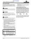
9. Carefully check cutting edges of blades in relation to
blade carrier rotation to ensure correct blade
placement. Blade rotation is counterclockwise with
cutting edge leading. Airfoil (lift) must be oriented
towards the top of the deck.
IMPORTANT: Replace cutting blades in pairs with
genuine Land Pride blades only. Replacing single
blades can result in an out-of-balance condition that
will contribute to premature bearing wear/breakage
and/or structural cracks in gearbox and/or deck.
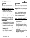
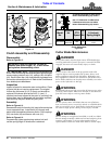
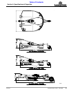
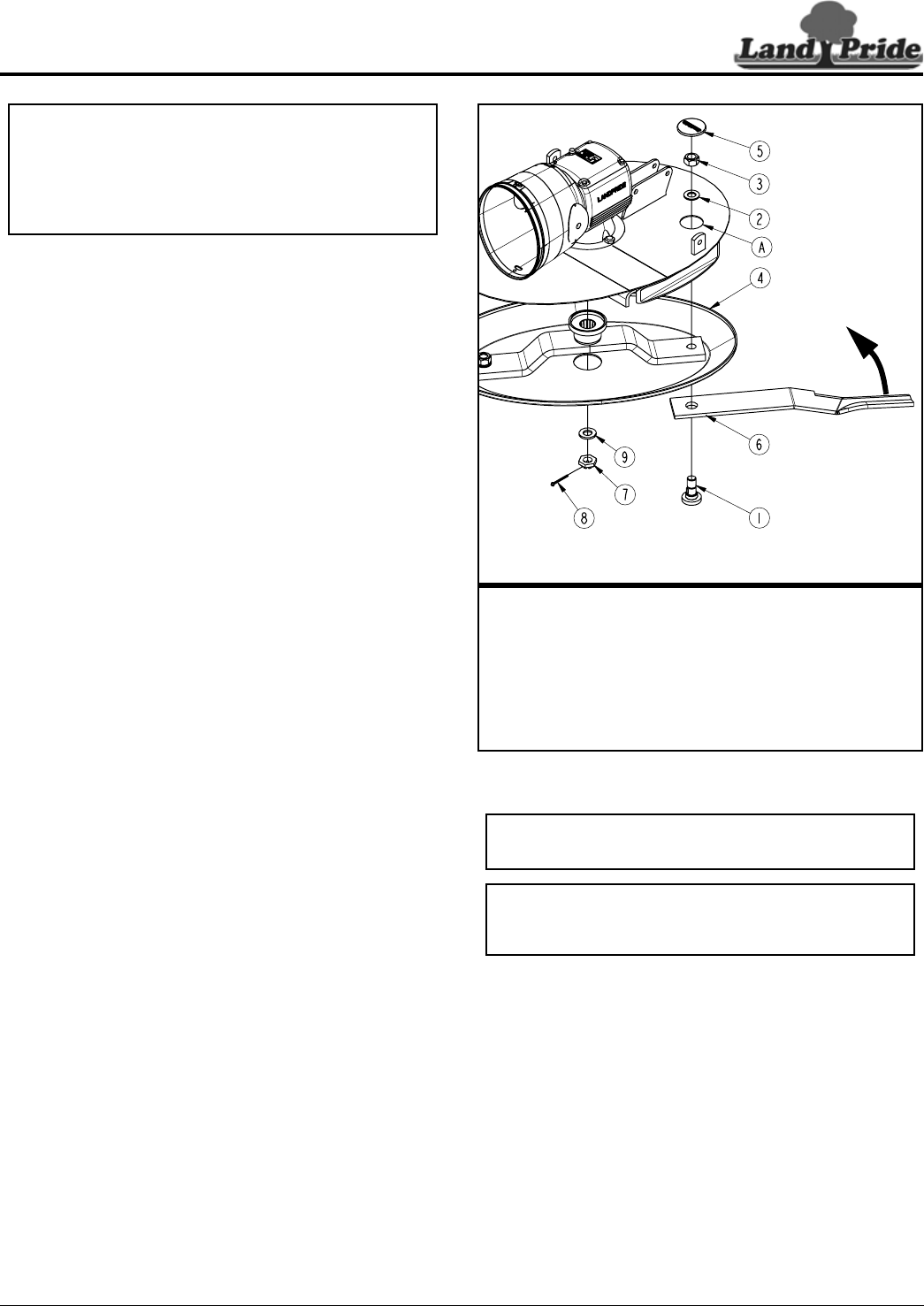
Cutter Blade Assembly (Counterclockwise Rotation)
Figure 4-1
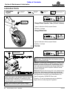
10. Insert blade bolt (#1) through blade (#6), dish
pan (#4), and flat washer (#2). Secure blade with a
new locknut (#3) and torque to 450 ft-lb.
11. Repeat step 10 for the other blade.
12. Replace access cover (#5).
13. If replacing dishpan (#4), nut (#7) on gearbox output
shaft should be torqued to 450 ft-lbs. minimum and
cotter pin (#8) installed with both legs bent opposite
directions around the nut.
33138
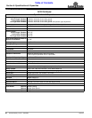
Land Pride Cutter Blade Parts
Item Part No. Part Description
318-586A BLADE BOLT KIT (items 1, 2, & 3 below)
1 802-277C BLADE BOLT 1 1/8-12 x 3 7/16 WITH KEY
2 804-147C WASHER FLAT 1 HARD ASTMF436
3 803-170C NUT HEX TOP LOCK 1 1/8-12 PLATE
4 312-818H 27 OVAL DISHPAN WELDMENT
5 840-273C PLUG LP 3" ID RUBBER
6 820-138C STANDARD BLADE 1/2" x 4" x 31" LG. CCW
IMPORTANT: Examine blade bolts (#1) and flat
washers (#2) for excessive wear and replace if worn.
IMPORTANT: Locknuts can loose their ability to lock
properly once removed. Always use a new locknut
when installing blades.