


8
Section 1: Assembly & Set-up
RCF2784 Rotary Cutters 326-364M
12/15/15
Table of Contents
Section 1: Assembly & Set-up
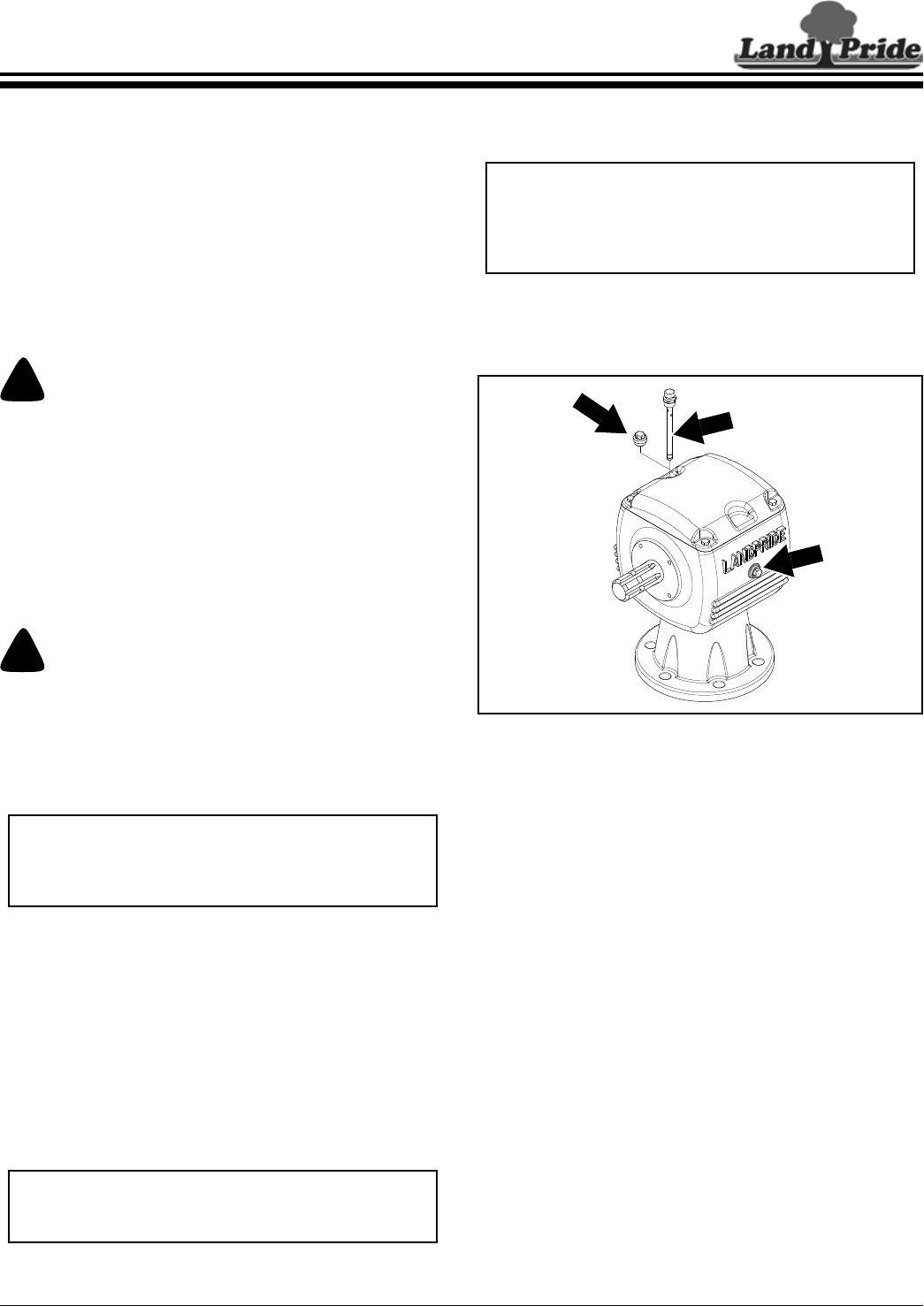
Gearbox Vented Dipstick
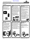
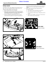
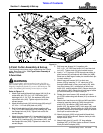
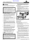
Refer to Figure 1-1:
A vented dipstick is shipped loose and packaged with the
Operator’s Manual. Remove temporary solid plug from
top of gearbox and replace with vented dipstick. See your
nearest Land Pride dealer if dipstick is missing.
Gearbox Vented Dipstick Installation
Figure 1-1
IMPORTANT: Rotary Cutters are shipped with a
solid plug in the gearbox to prevent loss of oil during
shipping and handling. The solid plug on top of the
gearbox must be replaced with a vented dipstick. Do
not operate cutter without vented dipstick installed.
30216
DO NOT
OVERFILL!
Oil Level
Plug
Remove
Solid Plug
Install
Vented Dipstick
Tractor Requirements
Tractor horsepower and hitch category should be within
the range noted below. Tractors outside the horsepower
range must not be used.
Tractor Horsepower Rating . . . . . . . . . . .60 to 130 HP
Hitch Type:
3-Point . . . . . . . . . . . . . . . . . . .Category Cat lI & lII
Pull-Type . . . . . . . . . . . . . . . . . . . . . . . . . .Draw Bar
PTO Speed. . . . . . . . . . . . . . . . . . . . . . . . . .540 RPM
Hydraulic Outlets (Pull-Type) . . . . . . . . . Single Outlet
Tractor Weight . . . . . . . . . . . . . . See Warning Below
!
WARNING
Ballast weights may need to be added to your tractor to
maintain steering control. Refer to your tractor operator’s
manual to determine proper ballast requirements.
Torque Requirements
Refer to “Torque Values Chart” on page 40 to determine
correct torque values for common bolts. See “Additional
Torque Values” at bottom of chart for exceptions to
standard torque values.
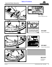
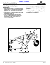
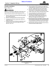
Uncrating Instructions
!
WARNING
Always secure cutter with an overhead crane, fork lift, or
other suitable lifting device before removing hardware bags,
shipping components, bands, lag screws, and hitch pins. The
cutter can suddenly fall causing serious injury or death.
1. Secure cutter with a hoist or other lifting device
before removing shipping hardware.
2. Unbolt rear chain guard from underside of deck.
Keep all attaching hardware for reassembly later.
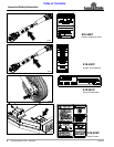
3. Cut shipping straps securing driveline and hitch
straps to the shipping crate. Remove driveline from
shipping crate and pivot hitch straps down gently.
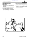
4. Remove lag screws securing front face of cutter to
the crate.
5. Using lifting device, remove tension on hitch pins
securing clevis plates to shipping crate.
6. Remove hitch pins from clevis plates and lift cutter
from shipping crate.
7. Gently lower cutter onto the working area. Be careful
not to allow hitch straps to fall onto the manual tube.
IMPORTANT: The rear chain guard is shipped
attached to the underside of the deck and must be
removed before putting cutter into service or the
cutting blades will hit the guard.
NOTE: When lowering cutter onto the working area,
keep hitch straps from falling onto the manual tube
and breaking the tube.