


13
Section 1: Assembly & Set-up
12/15/15
RCF2784 Rotary Cutters 326-364M
Table of Contents
!
WARNING
Do not over-speed PTO or machine breakage may result.
Some tractors are equipped with multispeed PTO ranges. Be
certain your tractor’s PTO does not exceed 540 RPM.
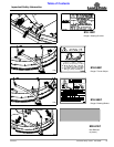
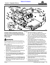
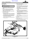
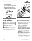
Refer to Figure 1-5 on page 12:
1. Park tractor on a level surface. Slowly engage tractor
3-Point lift lever to raise cutter until gearbox input
shaft is in line and level with the tractor PTO shaft.
2. Place gear selector in park, set park brake, shut
tractor off and remove switch key.
3. Support cutter deck at this height with support jacks
or blocks to keep cutter from drifting down.
4. Remove rubber protective sleeve (#8) from gearbox
input shaft and discard.
5. Unsnap one end of access doors (#9) and rotate
doors open.
6. Slide slip-clutch end of driveline (#11) onto gearbox
input shaft until hole in driveline yoke aligns with
groove in gearbox shaft. Insert M12 x 1.25 x 65mm
GR8 bolt (#2) and secure with flat washer (#4) and
hex nylock nut (#3). Tighten nylock nut to the correct
torque.
7. Push/pull on driveline yoke to be sure it is securely
fastened to the gearbox shaft.
8. Rotate access doors (#9) closed and snap in place.
9. Pull back on driveline yoke collar (#11) and push
driveline yoke onto the tractor PTO shaft. Release
pull collar and continue to push driveline yoke
forward until pull collar locks in place.
10. Move driveline yoke back and forth several times to
make sure yoke is locked in place. If driveline yoke
will not lock in place, skip to “Check Driveline
Collapsible Length” on this page.
11. Continue with “Check Driveline Collapsible
Length”.
Check Driveline Collapsible Length
IMPORTANT: An additional driveline may be
required if cutter is to be used on more than one
tractor, especially if a Quick Hitch is used.
The driveline must be lubricated before putting it into
service. Refer to “Lubrication Points” on page 34.
The tractor’s PTO shaft and cutter gearbox shaft
must be aligned and level with each other when
hooking-up the driveline to the tractor.
IMPORTANT: A driveline that is too long can bottom
out causing structural damage to tractor and cutter.
Always check driveline collapsed length during initial
setup, when connecting to a different tractor, and
when alternating between using a quick hitch and a
standard 3-point hitch. More than one driveline may
be required to fit all applications.
1. Make sure driveline is properly installed and level
before checking driveline collapsible length. Refer to
“Driveline Installation” instructions on page 12.
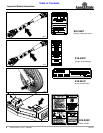
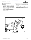
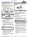
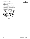
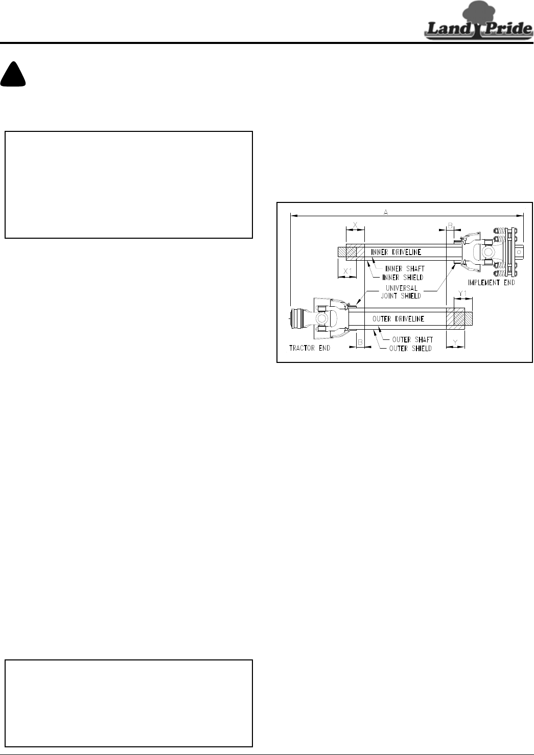
Refer to Figure 1-6:
2. With driveline level, measure (“B” dimension) back
from universal joint shield to end of outer driveline
shield as shown in Figure 1-6.
3. If measurement is 1” or more, skip to “Check
Driveline Interference” on page 14. If measurement
is less than 1", shorten driveline using instructions
provided below.
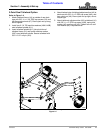
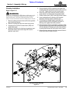
Driveline Shortening
Figure 1-6
Shorten Driveline
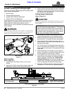
Refer to Figure 1-6:
Be sure to check driveline collapsed length first. If
required, shorten driveline.
1. Unhook driveline from tractor PTO shaft. Pull outer
and inner drivelines apart.
2. Reattach outer driveline to tractor PTO shaft. Pull on
inner and outer driveline yokes to be sure universal
joints are properly secured.
3. Hold inner and outer drivelines parallel to each other:
a. Measure 1" (“B” dimension) back from outer
driveline universal joint shield and make a mark at
this location on the inner driveline shield.
b. Measure 1" (“B” dimension) back from the inner
driveline universal joint shield and make a mark at
this location on the outer driveline shield.
4. Remove driveline from tractor PTO shaft and gearbox
shaft.
5. Measure from end of inner shield to scribed mark
(“X” dimension). Cut off inner shield at the mark. Cut
same amount off the inner shaft (“X1” dimension).
6. Measure from end of outer shield to scribed mark
(“Y” dimension). Cut off outer shield at the mark. Cut
same amount off the outer shaft (“Y1” dimension).
7. Remove all burrs and cuttings.
8. Continue with “Check Driveline Maximum Length”
on page 14.
33049