


14
Section 1: Assembly & Set-up
RCF2784 Rotary Cutters 326-364M
12/15/15
Table of Contents
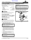
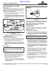
Check Driveline Maximum Length
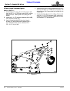
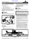
Refer to Figure 1-7:
The driveline maximum allowable length must, when fully
extended, have a minimum overlap of profile tubes by not
less than 1/2 the free length with both inner and outer
profile tubes being of equal length.
1. Apply multi-purpose grease to the inside of the outer
shaft and reassemble the driveline.
2. Assemble the two driveline profiles together with just
1/2 overlapping of the profile tubes as shown. Once
assembled, measure and record maximum allowable
length here. ________
Driveline Maximum Extended Length
Figure 1-7
3. Continue with “Check Driveline Interference” on
right side of this page.
Check Driveline Interference
1. Make certain driveline yokes are properly attached.
2. Start tractor and raise Rotary Cutter just enough to
remove support blocks from under the cutter.
3. Slowly engage tractor hydraulic 3-Point control lever
to lower cutter while checking for sufficient drawbar
clearance. Move drawbar ahead, aside, or remove if
required.
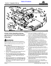
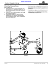
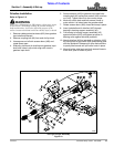
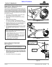
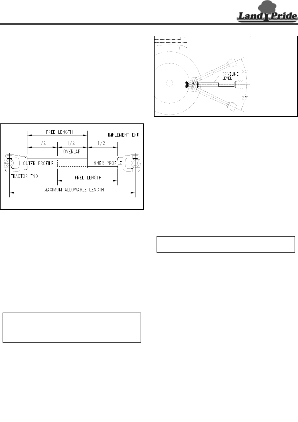
Refer to Figure 1-8:
4. With PTO off, raise implement fully up to make the
following checks below. If driveline exceeds any of
the limits listed, set tractor 3-Point lift limiter at a
height that will keep the driveline within its lift limits
and to avoid premature driveline breakdown.
• Driveline does not exceed 25
o
up.
• Driveline does not exceed maximum allowable
length recorded in step 2 under “Check Driveline
Maximum Length”.
24804
Outer Shielding has been removed for clarity.
IMPORTANT: Avoid premature driveline breakdown.
A driveline that is operating must not exceed an
angle of 25 degrees up or down while operating 3-
point lift.
Maximum PTO Driveline Movement During Operation
Figure 1-8
Pull-Type Cutter Assembly & Set-up
The following instructions are for assembling the
Pull-Type cutter. See page 9 for “3-Point Cutter
Assembly & Set-up” instructions.
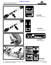
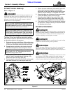
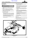
Hitch Assembly
The tongue, drivelines, dual tailwheel axle, and ratchet
jack option or hydraulic cylinder option will need to be
assembled to the deck.
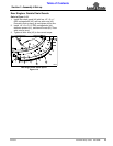
Refer to Figure 1-9 on page 15:
1. Discard 2 1/2" long bushing (not shown) shipped with
hitch pins (#1). Attach tongue (#7) to deck with hitch
pins (#1) and 1" long spacers (#4). Secure hitch pins
with linchpins (#21).
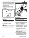
2. With bearing lock collar facing driveline (#25), attach
bearing support assembly (#5) to tongue (#9) with
bushings (#6), flat washers (#18), lock washer (#19),
hex nut (#15), and 5/8"-11 x 7 1/2" GR5 hex head cap
screw (#10). Tighten hex nut to the correct torque.
3. Attach spring hose loop mounting bracket (#3) to the
right-hand clevis with 3/8" -16 x 1" GR5 hex head cap
screw (#11) and lock nut (#16). Tighten lock nut to the
correct torque.
4. Attach spring hose loop (#22) to spring hose loop
mounting bracket (#3) with 3/8" -16 x 1" GR5 cap
screw (#9), flat washer (#17), and lock nut (#13)
Tighten lock nut to the correct torque.
5. Attach parking jack support stob (#2) to the left-hand
clevis lower hole with 3/4"-10 x 1 3/4" GR5 hex head
cap screw (#12) and lock nut (#16). Tighten lock nut
to the correct torque.
6. Attach parking jack (#27) to stob on tongue with
detent hitch pin (#28). Make certain detent hitch pin
is fully inserted.
24872
IMPORTANT: Be sure bearing lock collar in bearing
support assembly (#5) is facing driveline (#25).