


17
Section 1: Assembly & Set-up
12/15/15
RCF2784 Rotary Cutters 326-364M
Table of Contents
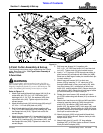
7. Attach clevis end of long leveling rod (#3) to mounting
bracket (#4) on the tongue with
3/4" x 1 1/2" clevis pin (#18), flat washer (#15), and
cotter pin (#17). Bend one or more legs of cotter pin
to keep it from falling out.
8. Attach clevis end of short leveling rod (#2) to
mounting lug on axle frame (#5) with 3/4" x 1 1/2"
clevis pin (#18), flat washer (#15), and cotter pin
(#17). Bend one or more legs of cotter pin to keep it
from falling out.
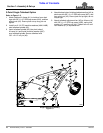
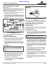
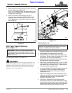
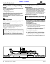
PTO to Drawbar Distance
Figure 1-11
Pull-Type Tractor Hook-up
Refer to Figure 1-11:
Adjust drawbar length so that center of drawbar hitch pin
hole and end of tractor PTO shaft is 14".
!
DANGER
A Crushing Hazard exists when hooking-up equipment to a
tractor. Do not allow anyone to stand between tractor and
implement while backing-up to implement. Do not operate
hydraulic 3-point lift controls while someone is directly
behind tractor or near implement.
22273
14"
8"
18" to 21"
IMPORTANT: Tractor PTO shaft, cutter driveline,
and/or gearbox can be damaged if distance from
end of tractor PTO shaft to center of hitch pin hole in
drawbar is not 14".
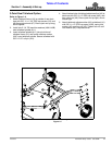
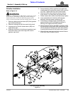
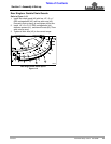
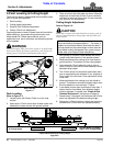
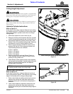
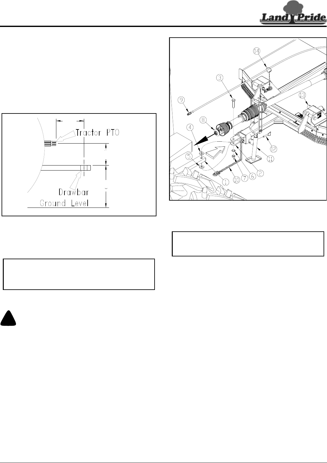
Tractor Hook-up (Standard Clevis Hitch Shown)
Figure 1-12
Refer to Figure 1-12:
1. Make certain jack stand (#11) is properly attached to
cutter hitch and properly secured with jack pin (#12).
2. Back drawbar (#1) close to clevis hitch (#2).
3. Drawbar should fit between upper and lower clevis
hitch plates. Raise or lower jack stand (#11) to align
clevis hitch (#2) with tractor drawbar (#1).
4. Back tractor up to cutter hitch until holes in drawbar
and clevis hitch are properly aligned.
5. Attach cutter to tractor drawbar with 1"-8 x 4 1/2" GR5
cap screw (#3), two flat washers (#4 & #5) as shown,
lock washer (#6), and hex nut (#7). Tighten hex nut
until lock washer is squeezed flat.
6. Lower jack stand (#11) until hitch weight is supported
by drawbar. Protect jack stand from damage by
removing it from the hitch and storing it on jack
support stob (#13).
7. Attach hitch safety chain (#10) to the tractor frame.
Adjust chain length to remove all slack except what is
necessary to permit turning. Lock chain hook
securely to the safety chain.
8. Pull back on driveline pull collar (#8) and push
driveline onto tractor PTO shaft. Release pull collar
and continue to push driveline yoke onto tractor PTO
shaft until pull collar locks into place. Pull on driveline
yoke to make certain yoke has locked in place.
33271
IMPORTANT: Jack attachment pin must be fully
inserted and secured before working on or around a
cutter not hooked to the tractor drawbar.