


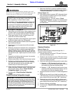
9
Section 1: Assembly & Set-up
12/15/15
RCF2784 Rotary Cutters 326-364M
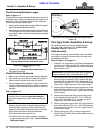
Table of Contents
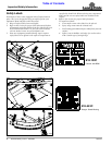
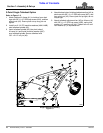
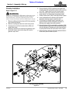
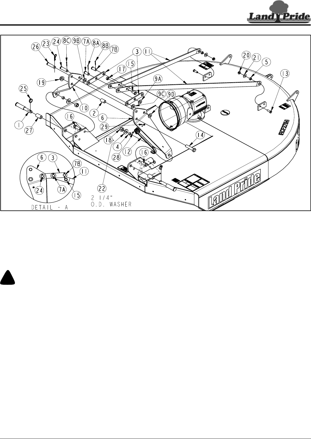
5. Bolt long rear braces (#11) together with
5/8"-11 x 1 1/2" GR5 cap screw (#15) and hex lock
nut (#17). Tighten lock nut to the correct torque.
6. Insert 1" x 2" clevis pin (#7B) through rear holes in
short braces (#3) and secure with cotter pin (#8B).
Bend one or both legs of cotter pin around clevis pin
to retain cotter pin.
7. Attach long rear braces (#11) to short rear
braces (#3) by inserting 1" x 2" clevis pin (#7A)
through middle hole in short rear brace (#3), both
long rear braces (#11), middle hole of short rear
brace (#3), and flat washer (#9A). Secure clevis pin
with cotter pin (#8A). Bend one or both legs of cotter
pin around clevis pin to retain cotter pin.
8. Rotate short rear braces (#3) around until clevis
pin (#7B) is above long rear braces (#11) as shown in
Detail-A.
9. Attach short rear braces to right and left-hand hitch
straps by inserting clevis pin (#24) through hitch
strap (#10), flat washer (#9B), both short rear
braces (#3), flat washer (#9C), hitch strap (#6), and
flat washer (#9D). Secure clevis pin (#24) with cotter
pin (#8C). Bend one or both legs of cotter pin around
clevis pin to retain cotter pin.
10. Attach clevis pin (#26) to right and left-hand hitch
straps (#10 & #6) as shown. Secure clevis pin with
hairpin cotter (#23).
11. Attach hitch pins (#1) and 2 1/2" long adapter
bushings (#27) to 3-Point clevis as shown. Secure
hitch pins with linchpins (#25).
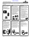
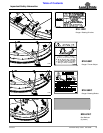
Hitch Assembly
Figure 1-2
33261
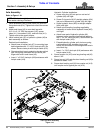
3-Point Cutter Assembly & Set-up
The following instructions are for assembling the 3-Point
cutter. See page 14 for “Pull-Type Cutter Assembly &
Set-up” instructions.
3-Point Hitch
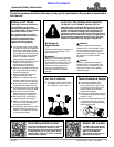
!
WARNING
Always secure cutter with an overhead crane, fork lift, or
other suitable lifting device before removing hardware bags,
shipping components, bands, lag screws, and hitch pins. The
cutter can suddenly fall causing serious injury or death.
Refer to Figure 1-2:
1. Attach right and left-hand hitch straps (#6 & #10) to
cutter deck with 7/8"-9 x 2 1/2" GR5 bolts (#16),
bushings (#4), 2 1/4" O.D. flat washers (#22), and
nylock hex nuts (#18). Tighten nylock nuts to the
correct torque.
2. Attach driveline hook (#12) to hitch strap (#6) using 5/
16"-18 x 1 1/4" bolt (#28) and nut (# 29).
3. Bolt left and right-hand hitch straps together with
1"-8 x 4 1/2" GR5 cap screw (#14), bushing (#2), and
hex flange lock nut (#19). Tighten lock nut to the
correct torque.
4. Attach long rear braces (#11) to rear deck lugs in the
holes shown with 5/8"-11 x 1 3/4" GR5 hex head cap
screws (#13), bushings (#5), flat washers (#21), and
hex flange lock nuts (#20). Tighten lock nuts to the
correct torque.