


40
Section 5: Maintenance & Lubrication
ZSR54, & ZSR60 Accu-Z Razor
®
Zero Turn Mowers 357-344M
Table of Contents
12/15/15
Belt Maintenance
!
DANGER
Before raising floor pan or removing pulley guards, make
certain blade engagement switch has been shut off, deck has
been properly blocked up, engine has been shut off, and switch
key has been removed for maximum safety. Replace all guards
and floor pan before putting mower back into service. Repairs
or maintenance requiring engine power should be performed
by trained personnel only.
Refer to Figure 5-15 and Figure 5-16 on page 41:
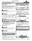
Replace belts that show signs of severe cuts, tears,
excessive weather checking, and cracking or burns
caused by slipping. Slight raveling of belt covering does
not indicate belt damage. Trim ravelings with a sharp
knife.
Inspect belt pulley grooves and flanges for wear. A new
belt, or one in good condition, should never run against
the bottom of the groove. Replace pulley when this is the
case, otherwise belt will lose power and slip excessively.
Never pry a belt onto a pulley as this will cut or damage
the fibers of the belt covering.
Keep oil and grease away from belts, and never use belt
dressings. Any of these will destroy the belt composition
in a very short time.
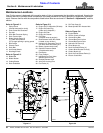
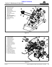
Deck Drive Belt Removal & Installation
Refer to Figure 5-15 on page 41:
1. Park mower on a flat surface.
2. Make sure blade engagement switch is (OFF),
control levers are fully (OUT), park brake is (ON) and
engine switch key is (OFF) and removed.
3. Place deck height in the lowest position.
4. Remove deck belt covers and raise floor platform.
5. Pull hitch pin (#8).
6. Release deck belt tension with by placing a socket
wrench with a 3/4" socket on the over-center-release
bolt (#9) and turning counterclockwise. This will
relieve the tension on the tension idler spring (#11).
7. Pull tension idler (#6) away from the belt to provide
maximum belt clearance.
8. Remove existing deck drive belt (#3).
9. Route new deck drive belt (#3) per the illustration
shown in Figure 5-15.
10. Re-tension idler (#6) by turning bolt (#9) clockwise
until over-center-release locks in place. Check belt
tension per the “Deck Drive Belt Adjustment” on
page 25.
11. Re-install hitch pin (#8).
12. Re-install deck belt covers and lower floor platform.
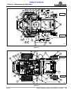
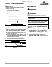
Ground Drive Belt Removal & Installation
Refer to Figure 5-16 on page 41:
1. Park mower on a flat surface.
2. Make sure blade engagement switch is (OFF),
control levers are fully (OUT), park brake is (ON), and
engine switch key is (OFF) and removed.
!
WARNING
Make sure engine and engine muffler are completely cooled
before working on and around the drive belt. Severe burns to
the body could result if engine and muffler have not cooled.
3. Place deck height in the lowest position.
4. Remove deck drive belt (#2) from deck drive pulley
(#1) as outlined in “Deck Drive Belt Removal &
Installation” instructions on this page. This belt
does not need to be removed from any of the deck
pulleys shown in Figure 5-15.
5. Back-up jam nuts (#8) 6 or more turns. One nut has
right-hand threads and the other nut has left-hand
threads.
6. Shorten take-up rod assembly (#7) by screwing
take-up rod (#9) until drive belt (#4) can be removed
from take-up pulley (#5).
7. Remove clutch locking bracket (#17) by removing
front right engine mounting bolt (#15) and nut (#16).
8. Slide drive belt off of take-up pulley (#5), pump
pulleys (#11), belt pulley (#10), and drive pulley (#3).
9. Slide new drive belt over drive pulley (#3), belt pulley
(#10), pump pulleys (#11), and take-up pulley (#5).
10. Lengthen take-up rod assembly (#7) by screwing
take-up rod (#9) until drive belt (#4) is secured on the
pulleys.
11. Re-tension drive belt (#4) per “Ground Drive Belt
Adjustment” instructions on page 25.
12. Re-install deck drive belt (#2) on the deck drive
pulley (#1). Make sure the belt is routed properly on
all deck pulleys.
13. Re-tension deck belt idler per the “Deck Drive Belt
Removal & Installation” instructions on this page.
14. Re-install clutch locking bracket (#17) with engine
mounting bolt (#15) and hex flange nut (#16). Make
sure locking bracket is seated in the clutch locking
notch and then tighten the mounting bolt to the
correct torque.