39
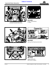
Section 5: Maintenance & Lubrication
ZSR54, & ZSR60 Accu-Z Razor
®
Zero Turn Mowers 357-344M
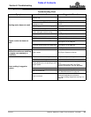
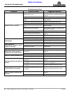
Table of Contents
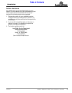
12/15/15
Evaporative Emission Control
System
All Land Pride Zero Turn Mowers will be EPA compliant
on the required January 1, 2012 date. Mowers that are
EPA compliant now have a decal on them stating:
“This Equipment meets U.S. EPA Evap. Standards”.
The Evaporative Emission Control System requires no
regularly scheduled maintenance but should be
inspected periodically, and thoroughly examined at least
once a year at the beginning of the mowing season:
1. Inspect all fuel system components including tanks,
vents, hoses, clamps, fuel filter, valves, and fittings
for leaks, cracks, and loose connections. Make
repairs as necessary.
2. The fuel tanks are equipped with tethered caps
Ensure tether is present and secured to the cap.
3. The fuel caps have been designed to provide audible
and tactile feedback indicating that proper sealing
has been achieved. Ensure that this function is
present and that no fuel leaks from the filler neck
during usage. If fuel leakage is ever noticed at this
point, the fuel cap must be replaced immediately.
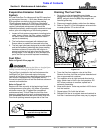
Fuel Filter
Refer to Figure 5-22 on page 44:
Empty fuel tank before replacing fuel filter to keep fuel from
leaking out and creating a fire/explosion hazard.
The fuel filter is installed in the fuel line between the
Left/Right Fuel Tank Valve and engine fuel pump.
Location of fuel filter will vary depending on which engine
your mower is equipped with. See engine owner’s
manuals for exact location of fuel filter and instructions on
removal and installation.
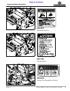
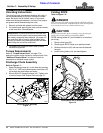
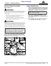
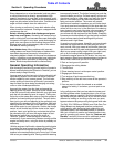
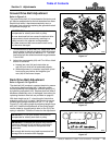
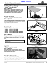
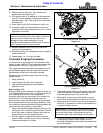
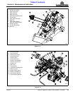
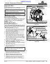
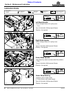
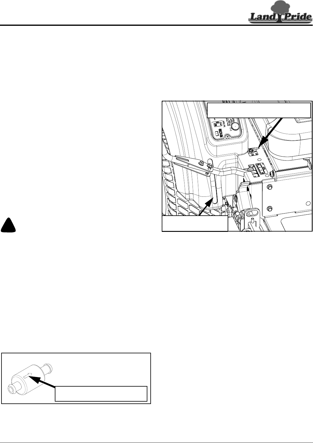
Refer to Figure 5-13:
Replace fuel filter annually at the beginning of each
mowing season or after every 100 hours of operation,
whichever occurs first. (Plugged filter considered
maintenance item) This will keep the fuel filter from
becoming plugged causing poor engine performance
and unexpected downtime. Be sure to install filter with
Flow Arrow pointing towards engine side of fuel line.
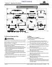
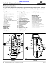
Fuel Filter
Figure 5-13
23803
(Flow Arrow) Indicates direction fuel
must flow through the filter.
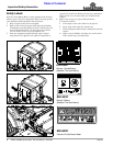
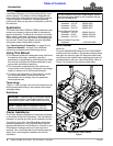
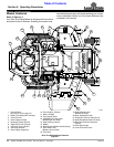
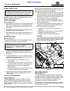
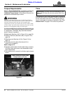
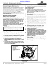
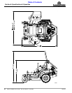
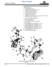
Draining The Fuel Tank
1. Park unit on a flat surface. Make sure blade
engagement switch is (OFF), both control levers are
(OUT), and park brake is (ON). Stop engine and
remove ignition key.
2. Disconnect negative battery cable from the battery.
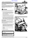
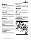
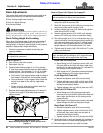
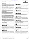
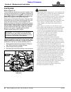
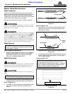
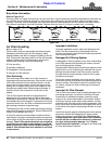
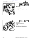
3. Refer to Figure 5-3: Find fuel selector valve and turn
to center position “O” to shut off fuel.
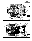
Fuel Shut-Off Valve
Figure 5-14
4. Trace fuel line from selector valve to fuel filter.
Remove line from fuel filter and place detached end
into an approved fuel container.
5. Turn selector valve to right tank and allow tank to
drain. Watch level of fuel in the fuel container. DO
NOT allow container to overflow, spilled fuel is
extremely flammable.
6. Allow tank to drain. Tanks may not drain 100% due to
fuel line location.
7. Repeat steps 5 & 6 with the left tank.
8. Reinstall fuel line to its original state and reattach to
fuel filter. Location and options many vary by engine.
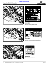
Left/Right Fuel Tank Valve
Center Position “O” as Shown is OFF
27766
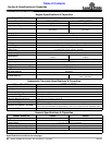
Fuel Sight Gauge
(Typical for both tanks)