


35
Section 5: Maintenance & Lubrication
ZSR54, & ZSR60 Accu-Z Razor
®
Zero Turn Mowers 357-344M
Table of Contents
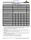
12/15/15
Electrical System
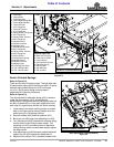
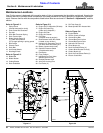
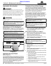
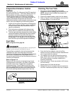
Refer to Figure 5-6:
The mower is equipped with a 12 volt negative ground
electrical system powered by a battery located under the
seat. When worn out, replace it with a maintenance-free
garden mower 12 volt BCI group UL1HD with 245 cold
cranking amps (CCA) or U1L-X with 300 CCA. Follow
manufacturer’s maintenance, safety, storing, and
charging specifications.
Battery
Figure 5-6
!
WARNING
Incorrect battery cable connections can damage the mower’s
electrical system and cause battery cables to spark. Sparks
around a battery can result in a battery gas explosion and
personal injury.
• Always disconnect negative (black) cable from battery
before disconnecting positive (red) cable.
• Always reconnect positive (red) cable to the battery’s
positive (+) post before reconnecting negative (black)
cable to the battery’s negative (-) post.
!
WARNING
Keep battery terminals from touching any metal mower parts
when removing or installing battery. Do not allow metal tools
to short between battery terminals and metal mower parts.
Shorts caused by battery terminals or metal tools touching
metal mower components can cause sparks. Sparks can cause
a battery gas explosion which can result in personal injury.
!
WARNING
Acid can cause serious injury to skin and eyes. Avoid skin
contact with battery acid and always wear eye protection
when checking the battery. Flush area with clean water and
call a physician immediately. Acid will also damage clothing.
!
WARNING
Do not overfill battery. Electrolytes may overflow and damage
paint, wiring and structure. Use soap and water when
cleaning the battery. Be careful not to get soap and water into
the battery. Use soda mixed in water to clean corrosion off the
terminals.
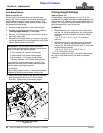
27753
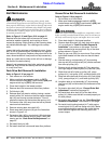
12 Volt Battery
!
WARNING
Do not allow an open flame near the battery when charging.
Hydrogen gas forms inside the battery. This gas is both toxic
and flammable and may cause an explosion if exposed to a
flame.
Common circuit problems are usually caused by
electrical shorts, corroded, or dirty terminals, loose
connections, defective wire insulation, or broken wires.
Switches, solenoids, and ignition components may also
fail, causing a shorted or open circuit.
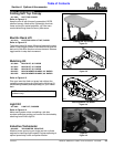
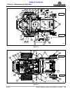
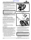
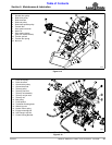
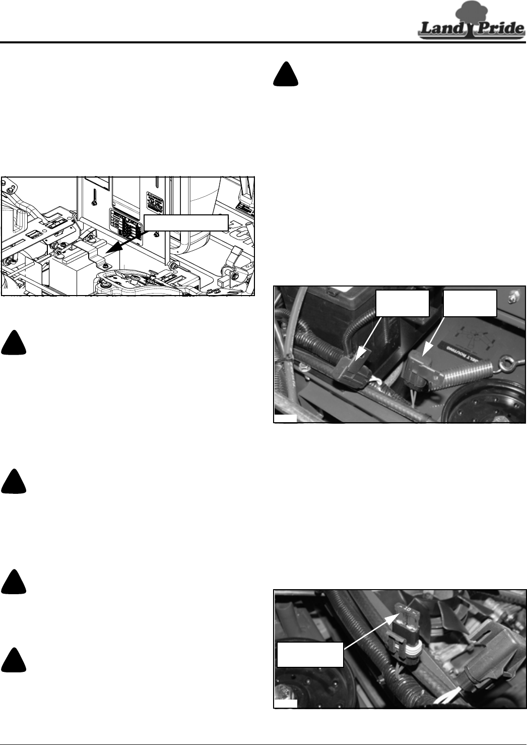
Refer to Figure 5-7:
The electrical system is protected by fuses located along
the wire harness beneath the seat.
The fuses are:
• Main - 20 Amp, blade type
• Clutch - 10 Amp, blade type
Wiring Harness Fuses
Figure 5-7
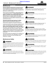
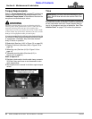
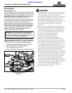
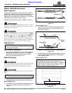
Refer to Figure 5-8:
Remove cover over the fuse to access the fuse.
Before diagnosing the electrical system, use a test light
or voltmeter to check battery voltage. If battery voltage is
satisfactory, check cleanliness and tightness of terminals
and ground connections. A general understanding of
electrical servicing and use of basic test equipment is
necessary for troubleshooting and repair.
Major overhaul or repair of starting motor and charging
system should be performed by trained technicians only.
10 AMP Fuse Shown W/Cover Removed
Figure 5-8
27958
10 Amp
Fuse
20 Amp
Fuse
27957
Uncovered
10 Amp Fuse