


PRELIMINARY ROUGH-IN
The floor structure beneath the unit must be able to
support a total weight of the unit and bather(s).
Refer to page 2, SPECIFICATIONS, for weight speci-
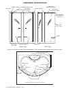
fications. Refer to COMPONENT IDENTIFICATION
on page 4 to help identify parts.
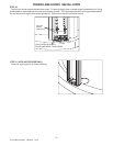
STEP 1
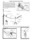
Provide an opening in the subfloor no less than 5" x 5"
square. This opening should be located on the center
lines of the shower base drain hole.
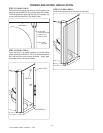
Install blocking in studwall for seat flange.
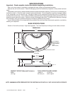
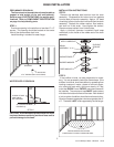
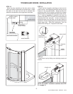
STEP 2
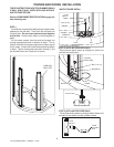
Remove the stainless steel strainer from the drain
assembly. Disassemble the locknut and two gaskets
from the back of the drain assembly. Apply a 1/4" bead
of caulking (silicone) to the drain hole and insert the drain
assembly. Replace the rubber washer, fiber washer,
and lock nut in that order. Hand tighten the locknut.
Remove excess sealant from finished side.
Apply a lubricant (common household liquid soap
works well) to the inside of the rubber seal of the drain
assembly.
STRAINER
DRAIN
ASSEMBLY
SILICONE
SEALANT
SHOWER BASE
RUBBER WASHER
FIBER WASHER
NUT
APPLY LUBRICANT
BASE INSTALLATION
INSTALLATION INSTRUCTIONS
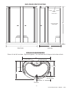
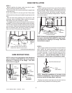
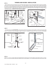
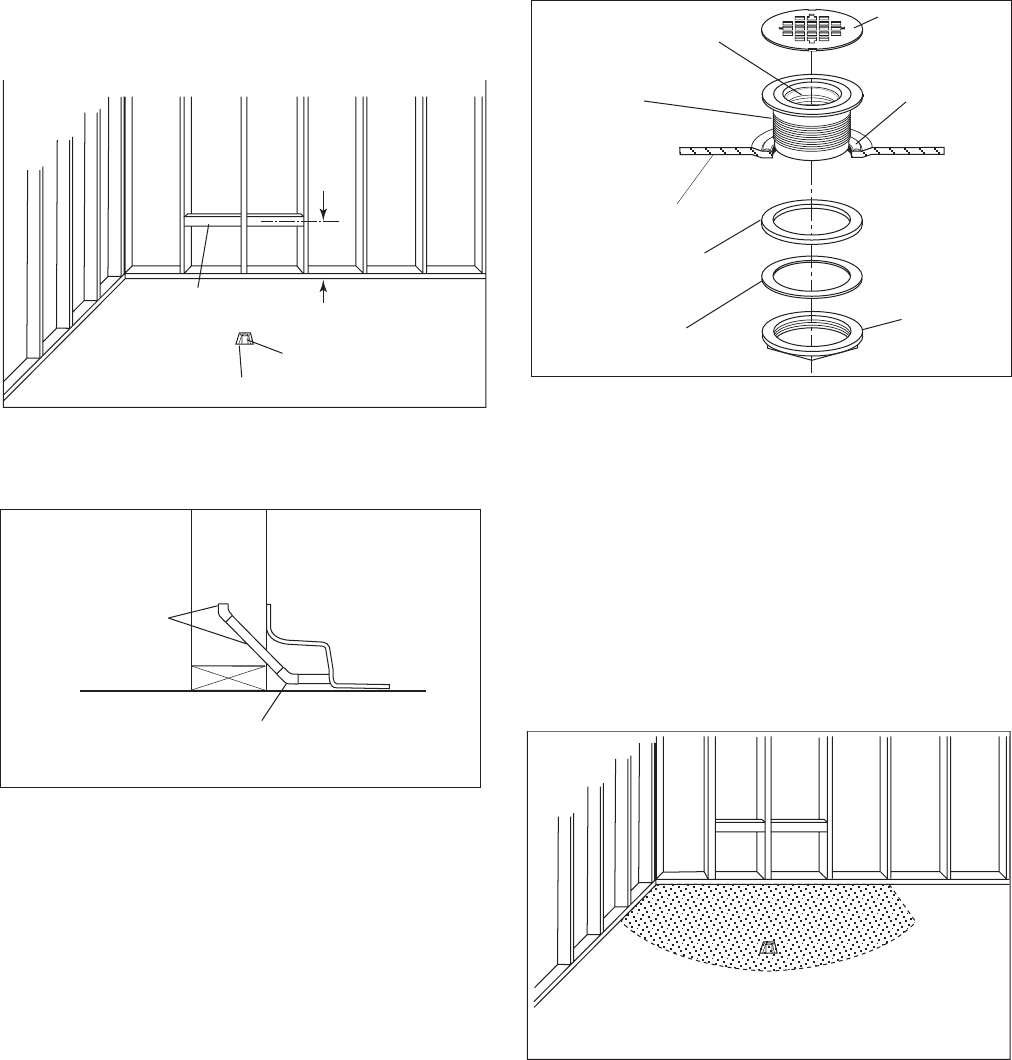
STEP 3
If the subfloor is level, no other preparation is neces-
sary. You can proceed to install the shower base. If the
subfloor is not level, level the subfloor by spreading floor
leveling compound, mortar, plaster or minimal expan-
sion structural foam with a minimum density of 5 lbs/
cubic feet EVENLY over ENTIRE area where base will
be installed. The compound used MUST make contact
with the entire bottom surface of the base. Both sides of
a joint or splice of subfloor should be level to each other.
Level and support waste pipe cutout area greater than 5"
x 5". The base is NOT to be supported by the tile flange.
SPREAD MORTOR OR LEVELING
COMPOUND ETC EVENLY OVER ENTIRE AREA
45° COPPER ELBOW
PROVIDED (2)
COPPER FITTINGS
AND TUBING
NOT PROVIDED
STUD
WALL
DETAIL 1
5"x5" OPENING (MIN. AS POSSIBLE)
2" WASTE PIPE
21"
C
L
BLOCKING
5
Jacuzzi Whirlpool Bath
©
BZ00000 03/05
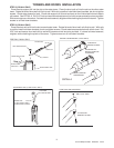
CAUTION: A nonflammable protective barrier must
be placed between soldering work and base unit to
prevent damage to the base.
WATER SUPPLY ROUGH-IN