


6
1
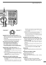
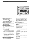
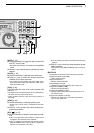
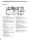
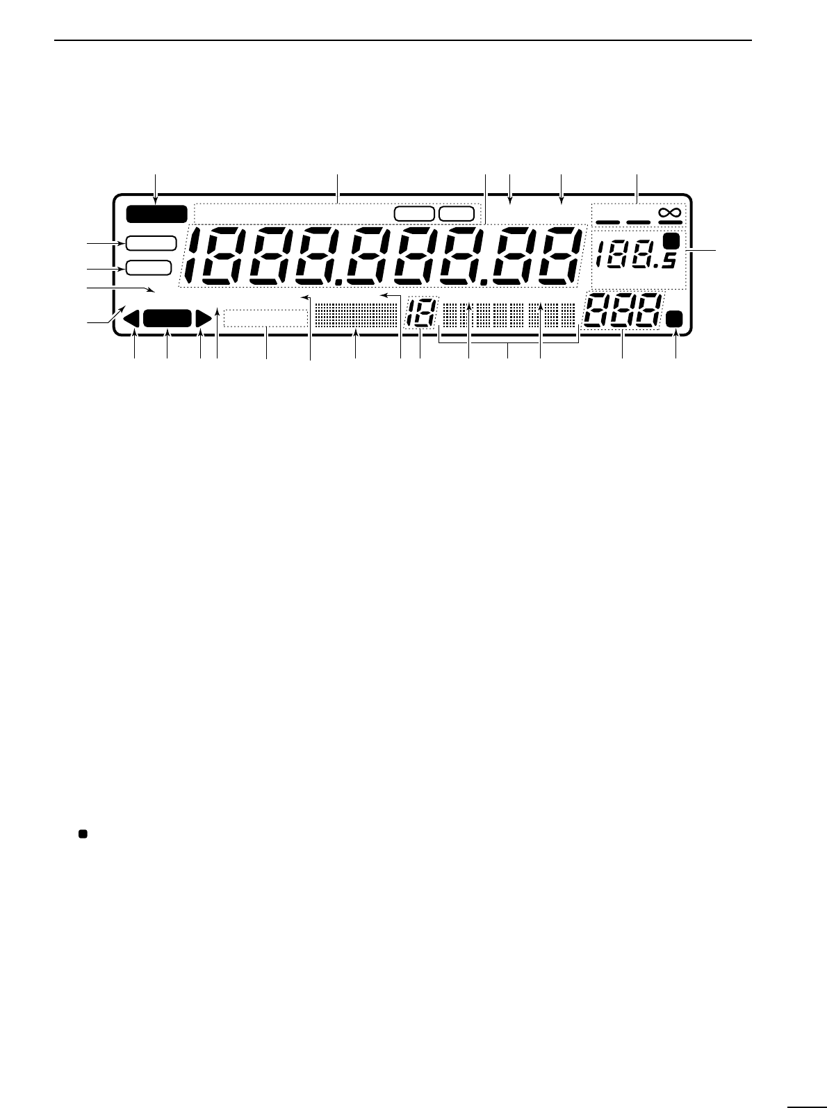
PANEL DESCRIPTION
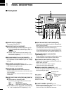
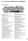
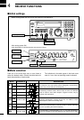
■ Function display
q
REMOTE INDICATOR (p. 35)
Appears when a level control command is received from a
PC via CI-V data.
•When this indicator appears, the control knob’s setting is
ignored.
•This indicator will disappear when the control knob is rotated.
wMODE INDICATORS (p. 13)
Show the operating mode.
eFREQUENCY READOUT
Shows the operating frequency.
rSKIP INDICATOR (p. 25)
➥Appears when the skip function is activated.
➥Flashes during scan when the skip function is ac-
tivated by the auto skip function.
tVSC INDICATOR (p. 26)
Appears when the voice scan control function is
activated.
y
SCAN RESUME CONDITION INDICATORS (p. 27)
Show the selected scan resume condition.
uTUNING STEP INDICATORS (p. 12)
Show the selected tuning step.
•
“” appears when a programmable tuning step is selected.
iTEMPORARY MEMORY INDICATOR (p. 19)
➥Appears when [M-SET] is pushed to indicate that
a frequency is being temporarily saved.
➥Disappears when the temporary memory is past-
ed into another memory channel.
oMEMORY CHANNEL READOUT (p. 17)
Shows the selected memory channel number.
!0SKIP CHANNEL INDICATOR (p. 25)
Appears when the selected memory channel is set
as a skip channel.
!1MEMORY NAME INDICATORS (p. 20)
Display names programmed into a memory, or scan
group.
!2SELECT CHANNEL INDICATOR (p. 23)
Appears when the selected memory channel is set
as a select channel.
!3BANK NUMBER INDICATOR (p. 17)
Shows the selected memory bank number.
!4BANK INDICATOR (p. 18)
➥Appears when the bank limit function is activated.
➥Flashes during scan when the bank limit function
is activated by the auto bank function.
!5BANK NAME INDICATOR (p. 20)
Displays names programmed into a bank.
!6AUDIO PEAK FILTER INDICATOR (p. 15)
“APF” or “APF-N” appears when the audio peak fil-
ter function is activated.
!7ATTENUATOR INDICATORS
Appear when the RF attenuator is activated.
!8AUTOMATIC GAIN CONTROL INDICATOR (p. 15)
AGC-F appears when AGC fast is selected; no indi-
cation appears when AGC slow is selected.
!9RECEIVE INDICATOR
Appears while receiving.
@0FM CENTER INDICATORS (p. 14)
Appear when the received signal is not tuned to its
center frequency.
@1NOISE BLANKER INDICATOR (p. 15)
Appears when the noise blanker circuit is activated.
@2AFC INDICATOR (p. 14)
Appears when the automatic frequency control
function is activated in either FM or WFM modes.
@3LOCK INDICATOR (p. 12)
Appears when the main dial or front panel switches
are locked.
@4SLEEP INDICATOR (p. 29)
Appears when the sleep timer is set.
P
REMOTE
WFM
RECV
AMUSBLSBCW
BANK
10-ATT-20
APF-NAGC-FAFCNB
SEL-CH SKIP-CH
WIDE NAR
SKIP VSC
OFF
MHz kHz
DLY
SLEEP
LOCK
M
P
qwerty
u
io!0!1!2!3!4!5!6!7!8!9@0 @0
@1
@2
@3
@4