


33
9
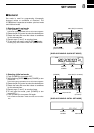
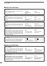
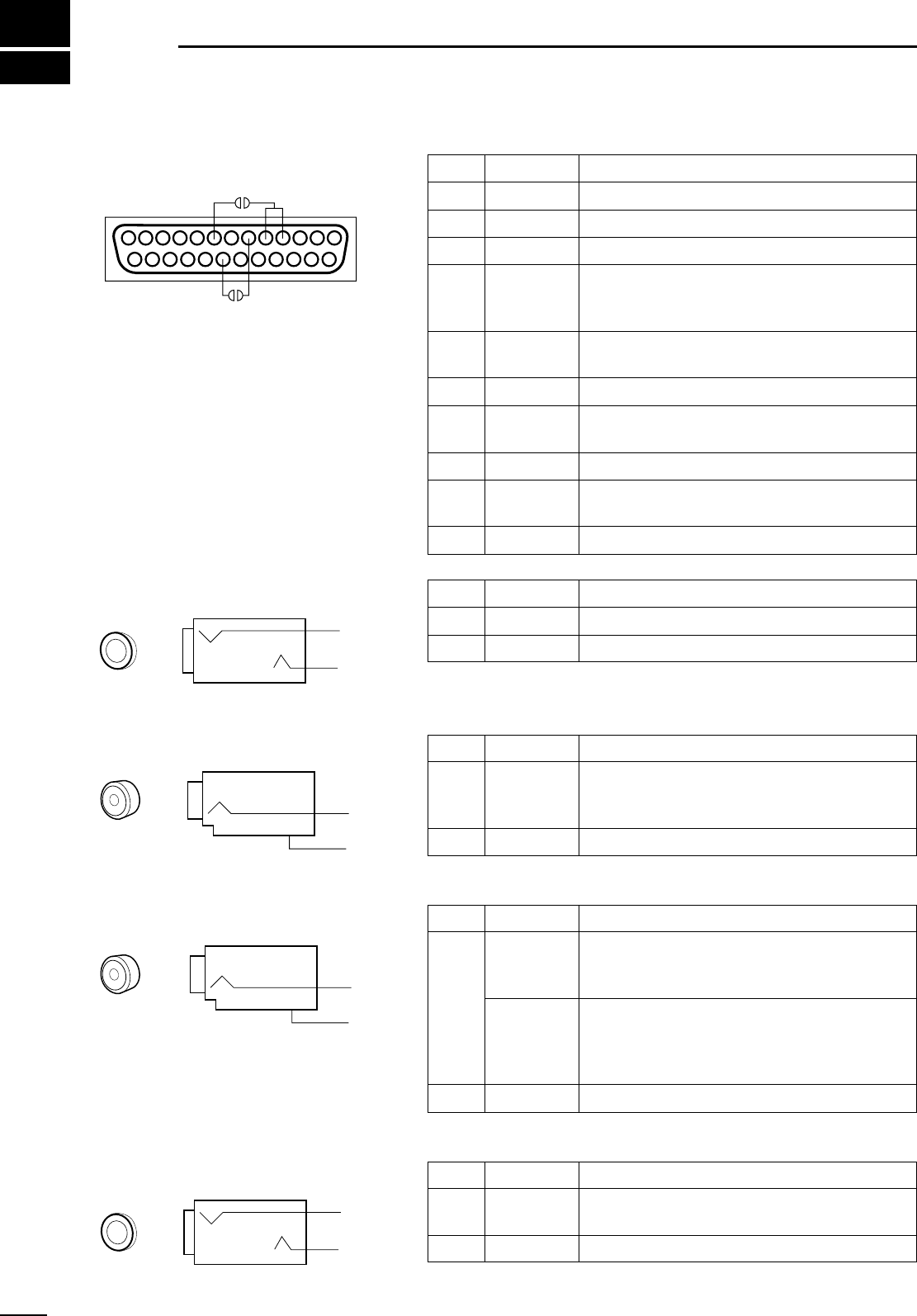
CONNECTOR INFORMATION
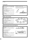
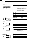
D RS-232C socket
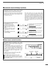
D Remote jack
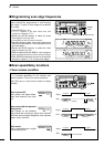
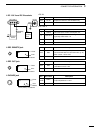
D IF OUT jack
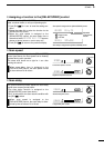
D AGC OUT jack
D External speaker
Pin Port name Description
1
GND Grounded.
2 RXD Input port for CI-V format data; +12V/–12V.
3 TXD Output port for CI-V format data; +12V/–12V.
4
5
RTS
CTS
Shorten these ports inside.
Can be connected to pin 8 (DCD) via the inter-
nal circuit board (‘coffee beans’).
6 DSR
NC; can be connected to pin 20 (DTR) via the
internal circuit board (‘coffee beans’).
7 GND Grounded.
8 DCD
NC; can be connected to pins 4 and 5 (RTS/CTS)
via the internal circuit board (‘coffee beans’).
9–19 NC No connection.
20 DTR
NC; can be connected to pin 6 (DSR) via the
internal circuit board (‘coffee beans’).
21–25 NC No connection.
13 1
25 14
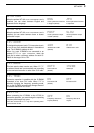
Pin Port name Description
Inner REMOTE Input/output port for CI-V format data; +5 V/0 V.
Outer GND Grounded.
Pin Port name Description
Inner IF OUT
Frequency:10.7 MHz
Output level:–60 dBm (with –50 dBm input from
an antenna connector in WFM mode)
Outer GND Grounded.
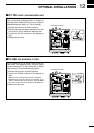
*Output is selectable with an internal jumper pin (p. 16).
Pin
Port name Description
Inner*
AGC out
Output voltage:1 to –2.4 V DC
(signal strength weak to strong)
Output impedance:2.2 MΩ
Audio detect
Output level:200 mV rms
(at Mod.=1 kHz, Dev.=3.5 kHz)
Output impedance:4.7 kΩ
•Before the frequency de-emphasis stage.
•Usable for FM only (not including WFM).
Outer GND Grounded.
Pin Port name Description
Inner AF out
Output level:More than 2 W
Output impedance:4–8 Ω
Outer GND Grounded.
3.5 mm (diam.) 2-conductor
Outer
Inner
RCA (phono) jack
Inner
Outer
RCA (phono) jack
Inner
Outer
3.5 mm (diam.) 2-conductor
Outer
Inner