


2
1
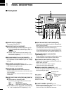
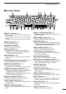
PANEL DESCRIPTION
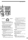
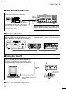
!2AUDIO PEAK FILTER CONTROL [APF] (p. 15)
Adjusts the audio peak filter setting to pick up a de-
sired audio frequency. Only valid when the [APF]
switch is ON.
•Clockwise rotation adjusts the filter setting higher; coun-
terclockwise rotation adjusts the filter setting lower.
!3
ATTENUATOR SWITCHES [10dB]/[20dB]
Push to activate one of the attenuators.
➧Push [10dB] to activate the 10 dB attenuator.
➧Push [20dB] to activate the 20 dB attenuator.
➧Push [10dB]+ [20dB] to activate the 30 dB attenuator.
•10 dB and 30 dB attenuator cannot be used below 500 kHz.
!4AUDIO PEAK FILTER SWITCH [APF] (p. 15)
➥Push momentarily to toggle the audio peak filter
circuit ON and OFF.
•Use the [APF] control to adjust the center of the audio
peak passband.
➥When the audio peak filter circuit is ON, push for
1 sec. to toggle the filter setting between normal
and narrow.
•‘Narrow’ is available for SSB, CW and AM only.
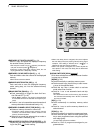
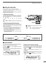
!5
SPEECH/LOCK SWITCH [SPCH/LOCK]
➥Push momentarily to activate the voice synthesiz-
er function and have the displayed frequency
announced.
•An optional UT-102
SPEECH SYNTHESIZER UNIT
is nec-
essary to activate the voice synthesizer function (p.38).
•Automatic announcement at signal detection during
scan is available. Refer to the “REC SPCH” item on
p. 31 for details.
➥
Push for 1 sec. to activate the lock function (p.12).
•Push for 1 sec. again to cancel the lock function.
•The lock function action can be selected in set mode
to cover the main dial only, or to cover both the main
dial and front panel switches.
!6
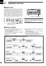
TUNING STEP SWITCHES [TS▲]/[TS▼] (p. 12)
Select the tuning step for the main dial. Push [TS▲]
to select a larger tuning step; push [TS▼] to select
a smaller tuning step.
•10 Hz, 50 Hz, 100 Hz, 1 kHz, 2.5 kHz, 5 kHz, 9 kHz, 10
kHz, 12.5 kHz, 20 kHz, 25 kHz, 100 kHz and 1 MHz are
selectable.
•Programmable tuning steps can be set between 0.5 and
199.5 kHz.
➠To set programmable tuning steps, enter the desired
steps via the keypad, then push [TSY]or [TSZ].
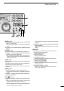
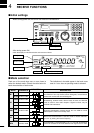
!7
MAIN DIAL
Changes the operating frequency, set mode contents,
etc.
!8BRAKE ADJUSTMENT SCREW
Adjusts the main dial tension.
!9FUNCTION DISPLAY (p. 6)
Shows the selected frequency, mode, memory
name, etc.
@0S-METER
➥Shows the strength of the received signal.
➥Shows the squelch threshold level when the
[SQUELCH] is rotated past the center position.
MEMO
SEL SKIP VSC
DLY
SCAN/
NAME
SCAN SET
PROG AUTO PRIO
M-SET BANK
M-CL MW
DELAY/SPEEDM-CH
D/S
1 QZ
GHI
PRS TUV WXY
ENT
BANK
BANK
JKL MNO
ABC DEF
.
;
,
4
78
0CE
ENT
M-CH
.
9
56
23
!9
!5
!6
!8
!7
SEL-CH SKIP-CH
OFF
kHz
DLY
M
IC-R8500
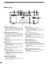
Center frequency
is shifted up.
Center frequency
is shifted down.