


Maintenance
to see if the wheel stops. If not, repeat the
above adjustment procedure.
6. Make this adjustment on both sides.
7. After adjustments are made and the wheels
stop when the drive levers are in the neutral
position, tighten the nuts against the yokes.
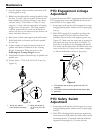
• Adjust Hydro Control Linkages:
1. Place the speed control lever in the “neutral”
position. This adjustment is again made with
rear of machine on jack stands and engine
running at full throttle. OPC levers will have
to be held down and the park brake must be
disengaged whenever speed control levers are
moved out of the neutral position.
Note: The neutral lock latches should be
“unlocked” and in the forward position.
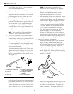
2. Loosen the front nut on left hydro control
linkage as shown in Figure 20. Turn the rear
control linkage adjusting nut counterclockwise
until wheel rotates forward. Turn the rear nut
of left control linkage clockwise 1/4 of a turn
at a time, stopping to move the speed control
forward and back to neutral, until left wheel
stops rotating forward.
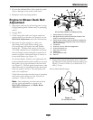
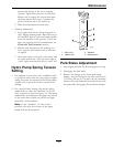
Turn the rear nut an additional 1/2 turn and
tighten the front nut making sure not to put
a bind on the linkage. Make sure at part of
linkage is perpendicular to pin part of swivel
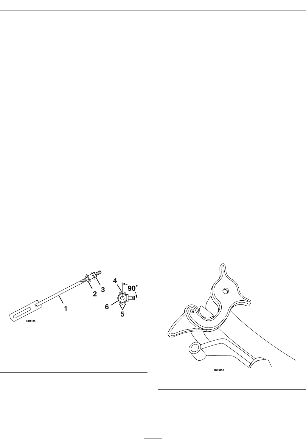
(see Figure 21).
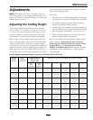
Figure 21
1. Left Hydro Control Link
(left side shown)
4. Linkage is perpendicular
to pin (correct position)
2. Front nut 5. Linkage in incorrect
position
3. Rear nut
6. End view of swivel
After adjusting the left hydro control linkage,
move the speed control lever to the mid-speed
position and then back to the neutral position.
Recheck the left drive wheel rotation to see if
further adjustment is necessary - be sure the
speed control lever is in the neutral position.
Note: If inconsistent neutral occurs,
check to be sure both springs are properly
tightened on the speed control lever under the
console–especially the rear pivot spring.
Repeat above adjustments if necessary.
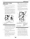
3. Place the speed control lever in neutral. Adjust
the right side linkage by turning the quick track
knob counterclockwise until the tire begins to
rotate forward. Begin to retighten the knob
clockwise about 1/4 turn at a time, stopping
to move the speed control forward and back
to neutral. Recheck the drive wheel rotation
to see if further adjustment is necessary.
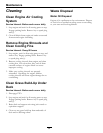
4. The spring that keeps tension on the knob
should normally not need adjustment.
However, if adjustment is needed, adjust to
where length of spring is about 1 inch (2.5 cm)
between the washers. Adjust spring length by
turning nut at front of spring.
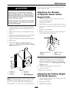
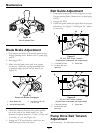
• Drive Lever Linkage Adjustment:
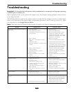
1. With rear of machine still on jack stands and
engine running at full throttle, disengage
the park brake and move the speed control
lever to the midway position. Move the
respective drive lever upward until it reaches
the neutral position and engage neutral lock
latches (Figure 22). If the tire rotates in either
direction, the length of the drive lever link will
need to be adjusted.
Figure 22
2. Adjust the linkage length by loosening the jam
nuts at both ends of the linkage and rotating
the linkage in the ball joints. Lengthen the
linkage if the tire is turning in reverse and
34