


Operation
Product Overview
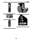
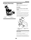
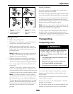
Figure 3
1. ECS Handles 3. Fuel Cap
2. Controls 4. Blade Spacers
Operation
Note: Determine the left and right sides of the
machine from the normal operating position.
Controls
Operator Presence Control (OPC)
Levers
Located on the upper handle assembly directly above
the handle grips.
When these levers are depressed, the OPC system
senses that the operator is in the normal operator’s
position. When the levers are released, the OPC
system senses that the operator has moved from the
normal operating position and will kill the engine if
either the speed control lever is not in the neutral
position or the PTO is engaged (see Figure 4).
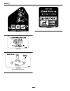
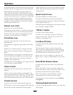
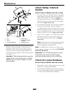
Figure 4
1. OPC Lever
3. Neutral Lock Latch
2. Rotate neutral lock latch
downward for neutral
lock position
4. Drive Lever in neutral
position
Drive Levers
Located on each side of the upper handle assembly
ahead of and below the handle grips.
These levers individually control the speed and
direction of each drive wheel. When the speed control
lever is moved out of the neutral position and the
neutral lock latches are moved into the drive position,
15