Maintenance
4. Stop the engine, remove the key and wait for all
moving parts to stop.
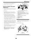
5. Blades may be adjusted for cutting height by using
the four 1/4 inch (.64 cm) spacers found on the
blade spindle bolts (factory setting is two above
and two below). This allows a 1 inch (2.5 cm)
range in 1/4 inch (.64 cm) increments of cutting
height in any axle position. The same number
of blade spacers must be used on all blades to
achieve a level cut (two above and two below, one
above and three below, etc.).
6. Raise front of deck and support with jack stands.
7. Hold blade bolt on bottom and loosen spindle
nut on top.
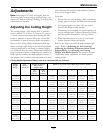
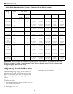
8. Adjust number of spacers between bottom of
spindle and blade as indicated in the Cutting
Height Adjustment Table and notes in the
Adjusting the Cutting Height section.
9. Install unused spacers between top of spindle and
spindle nut.
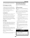
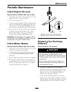
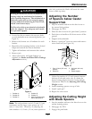
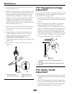
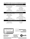
10. Torque bolt to 75–80 ft-lb (102–109 N-m) (see
Figure 11).
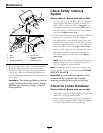
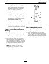
Figure 11
1. Spring disc washer
(cone towards bolt head)
2. Blade bolt torque to
75–80 ft-lb (102–109
N-m)
PTO Engagement Linkage
Adjustment
Located between the PTO engagement bellcrank and
PTO engagement assist arm beneath the front, left
hand corner of the engine deck.
1. Stop engine and wait for all moving parts to stop.
Engage parking brake. Remove key or spark plug
wire(s).
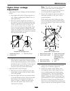
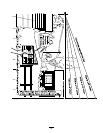
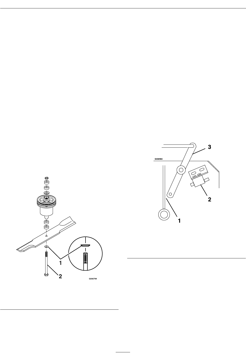
2. With PTO engaged (lever pulled up, adjust the
linkage length to where the lower end of the
bellcrank just clears the axle support gusset (see
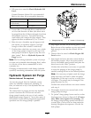
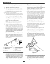
Figure 12). Make sure the assist arm is against the
rear assist arm stop on the deck (see Figure 13).
Push the lever down to the disengaged position.
The assist arm should contact the front assist arm
stop on the deck. If it does not contact, readjust
so that the bellcrank is closer to the gusset.
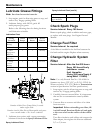
Figure 12
1. The bellcrank just clears the gusset with the PTO
engaged
2. PTO Safety Switch (located beneath the engine deck)
3. Bellcrank
PTO Safety Switch
Adjustment
1. Stop engine and wait for all moving parts to stop.
Engage parking brake. Remove key or spark plug
wire(s).
2. With PTO disengaged and assist arm against the
front assist arm stop, adjust the blade safety switch
mounting bracket (if needed) until the bellcrank
depresses the plunger by 1/4 inch (.64 cm).
30