


Maintenance
CAUTION
Raising the mower for service or maintenance
relying solely on mechanical or hydraulic
jacks could be dangerous. The mechanical or
hydraulic jacks may not be enough support
or may malfunction allowing the unit to fall,
which could cause injury.
Do Not rely solely on mechanical or hydraulic
jacks for support. Use adequate jack stands
or equivalent support.
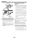
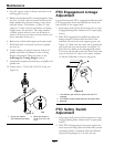
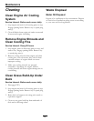
4. Loosen but do not remove the top two bolts
on each hydraulic motor mounting bracket (see
Figure 9).
5. Remove the bottom sets of hardware for each
bracket.
6. Reposition the mounting bracket to the desired
height and reinstall the bottom hardware.
7. Tighten all hardware and remount drive wheels.
8. Remove jack.
9. Adjust wheel drive and brake linkages as
required (see Brake and Wheel Drive Linkage
Adjustment section).
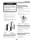
Figure 9
1. Position A 4. Position D
2. Position B 5. Position E
3. Position C
6. Axle Pivot Bolt-loosen
but Do Not remove
Note: The axle positions are in 1/2 inch (1.3 cm)
increments and the large caster spacers are 1/2
inch (1.3 cm) thick. Therefore, by adjusting the
same number of 1/2 inch (1.3 cm) caster spacers as
axle hole positions the blades will retain the same
front-to-back tip (rake).
Adjusting the Number
of Spacers below Caster
Support Hub
1. Stop the machine and move the drive levers to
the neutral lock position.
2. Disengage the PTO.
3. Place the drive levers in the “park brake” position.
4. Push down on handles to lift front casters off the
ground.
5. Support with jackstands.
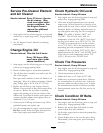
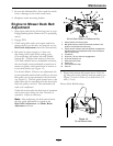
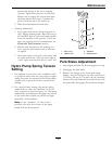
6. Remove “quick pin” from one caster and remove
caster from hub (see Figure 10).
Figure 10
1. Four 1/2 inch (127 mm)
spacers
3. 3/16 inch (4.8 mm)
spacer
2. Quick Pin 4. Caster support
7. Adjust the number of 1/2 inch spacers between
bottom of hub and caster yoke to obtain the
desired cutting height from the Cutting Height
Adjustment Table in the Adjusting the Cutting
Height section.
8. Install remaining spacers on top of hub.
9. Install “quick pin”.
10. Repeat for other caster.
Adjusting the Cutting Height
with Blade Spacers
1. Stop the machine and move the drive levers to the
neutral locked position.
2. Disengage the PTO.
3. Engage the park brake.
29