


Maintenance
Hydro Drive Linkage
Adjustment
• Adjust Speed Control Linkage and Neutral Safety
Switch:
1. Stop engine and wait for all moving parts to
stop. Engage parking brake. Remove key or
spark plug wire(s).
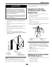
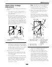
2. Move the speed control lever (located on
the console) to the full forward position and
check the orientation of the tabs on the ends
of the speed control crank (see Figure 19).
These tabs should be pointing straight down
at the 6 o’clock position or slightly forward.
Adjust the threaded yoke at the bottom of the
speed control linkage (see Figure 19) until the
tabs are positioned correctly.
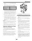
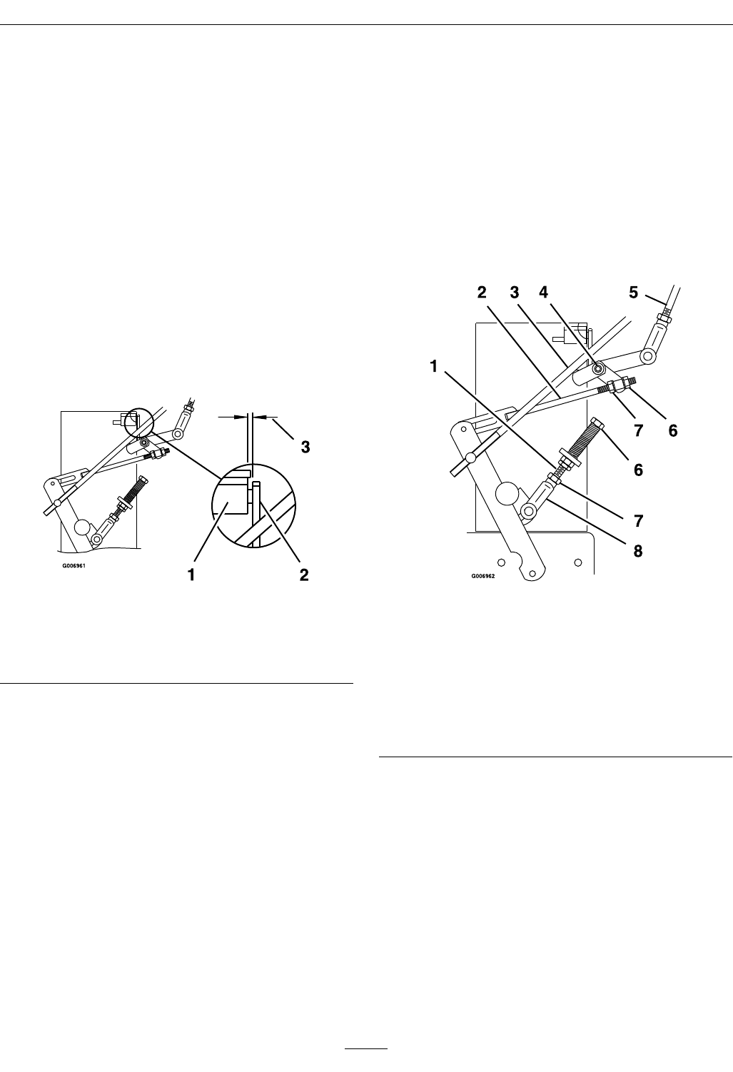
Figure 19
Viewed from Left Side of Unit
1. Neutral Safety Switch 3. 5/16 inch (.76 cm)
2. Actuating Tab
3. Pull the speed control lever back to neutral.
Check that the neutral safety switch actuating
tab has depressed the plunger of the switch so
that there is about 5/16 inch (.79 cm) between
the tab and the switch (see Figure 19). If
necessary, move the switch fore and aft.
• Adjust Neutral Control Linkages:
1. Raise the rear of the machine up onto jack
stands high enough to raise the drive wheels
off of the ground.
2. Start the engine and move the throttle ahead
to the full throttle position. Place the neutral
lock latches in the “forward” position as
shown in Figure 4. Release the park brake
and move the speed control lever to the
“mid-speed” position.
Note: The OPC levers must be held down
and the park brake must be disengaged
whenever the speed control lever is moved
out of neutral or the engine will kill.
3. Squeeze the respective drive lever until an
increased resistance is felt, this is where
neutral should be.
If the wheel turns while holding the drive
lever in neutral, the neutral control linkages
need to be adjusted. If the wheel stops then
go to step 7.
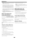
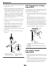
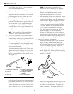
Figure 20
Viewed from Left Side of Unit
1. Neutral Control Linkage 5. Speed Control Linkage
2. Hydro Control Linkage
6. Adjust here-rotate at
approximately 1/4
turn increments and
re-check.
3. Drive Lever Linkage 7. Loosen nut
4. Speed Control Crank
8. Yoke
4. Loosen the nut against the neutral control
linkage yoke as shown in Figure 20.
5. Adjust the neutral control linkage until
the respective drive wheel stops when the
lever is pulled against the neutral spring
(neutral position). Turn the adjusting bolt
approximately 1/4 turn clockwise if the
wheel is turning in reverse or turn the bolt
approximately 1/4 turn counterclockwise if
the wheel is turning forward. Release the
drive lever to the forward drive position and
squeeze back into the neutral position. Check
33