


Maintenance
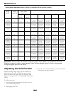
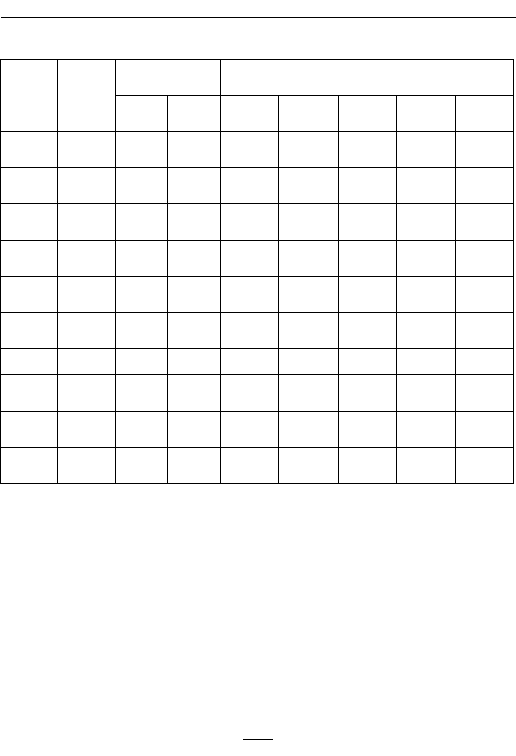
Cutting Height Adjustment Table (1 inch to 4 1/4 inches (2.5 cm-10.8 cm)) (cont'd.)
Number Of Spacers
Below Caster
Support Hub
Number of 1/4 inch (.64 cm) Blade Spacers Below Spindle
Cutting
Height
Range
Axle
Position
(Figure 9)
1/2
inch
(1.2 cm)
3/16
inch
(.48 cm)
4
3 2
1 0
2 1/8–
3 1/8 inches
(5.4–7.9 cm) C 2 0
2 1/8 inch
(5.4 cm)
2 3/8 inch
(6.0 cm)
2 5/8 inch
(6.7 cm)
2 7/8 inch
(7.3 cm)
3 1/8 inch
(7.9 cm)
2 1/4–
3 1/4 inches
(5.7–8.3 cm) C 2 1
2 1/4 inch
(5.7 cm)
2 1/2 inch
(6.4 cm)
2 3/4 inch
(7.0 cm)
3 inch
(7.6 cm)
3 1/4 inch
(8.3 cm)
2 1/2–
3 1/2 inches
(6.4–8.9 cm) C 3 0
2 1/2 inch
(6.4 cm)
2 3/4 inch
(7.0 cm)
3 inch
(7.6 cm)
3 1/4 inch
(8.3 cm)
3 1/2 inch
(8.9 cm)
2 3/8–
3 3/8 inches
(6.0–8.6 cm) D 2 1
2 3/8 inch
(6.0 cm)
2 5/8 inch
(6.7 cm)
2 7/8 inch
(7.3 cm)
3 1/8 inch
(7.9 cm)
3 3/8 inch
(8.6 cm)
2 1/2–
3 1/2 inches
(6.4–8.9 cm) D 3 0
2 1/2 inch
(6.4 cm)
2 3/4 inch
(7.0 cm)
3 inch
(7.6 cm)
3 1/4 inch
(8.3 cm)
3 1/2 inch
(8.9 cm)
2 3/4–
3 3/4 inches
(7.0–9.5 cm) D 3 1
2 3/4 inch
(7.0 cm)
3 inch
(7.6 cm)
3 1/4 inch
(8.3 cm)
3 1/2 inch
(8.9 cm)
3 3/4 inch
(9.5 cm)
3–4 inches
(7.6–10.1 cm) D 4 0
3 inch
(7.6 cm)
3 1/4 inch
(8.3 cm)
3 1/2 inch
(8.9 cm)
3 3/4 inch
(9.5 cm)
4 inch
(10.1 cm)
2 7/8–
3 7/8 inches
(7.3–9.8 cm) E 3 1
2 7/8 inch
(7.3 cm)
3 1/8 inch
(7.9 cm)
3 3/8 inch
(8.6 cm)
3 5/8 inch
(9.2 cm)
3 7/8 inch
(9.8 cm)
3 1/8–
4 1/8 inches
(7.9–10.5 cm) E 4 0
3 1/8 inch
(7.9 cm)
3 3/8 inch
(8.6 cm)
3 5/8 inch
(9.2 cm)
3 7/8 inch
(9.8 cm)
4 1/8 inch
(10.5 cm)
3 1/4–
4 1/4 inches
(8.3–10.8 cm) E 4 1
3 1/4 inch
(8.3 cm)
3 1/2 inch
(8.9 cm)
3 3/4 inch
(9.5 cm)
4 inch
(10.1 cm)
4 1/4 inch
(10.8 cm)
Important: Always adjust the Number of Spacers below Caster Hub to correspond to the Axle
Position as shown in table to obtain proper “rake” (blades should always be level to the ground
or tipped slightly down at the front).
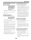
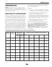
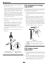
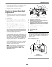
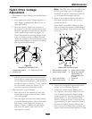
Adjusting the Axle Position
Desired cutting height range can be obtained by
adjusting the rear axle and placing caster spacers
above or below the caster arm (see Figure 9 and
Figure 10 along with the Cutting Height Adjustment
Chart).
To adjust rear axle:
1. Stop the machine and move the drive levers to
the neutral lock position.
2. Disengage the PTO.
3. Raise the rear of the machine up onto jack stands
and remove the drive wheels.
28