


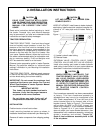
LOADER MOUNTED CONTROL VALVE
EQUIPPED WITH 2 OR 3 CONTROL HANDLES
OR TRACTOR REMOTE VALVE EQUIPPED WITH
2 OR 3 CONTROL HANDLES
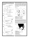
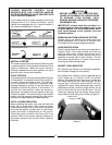
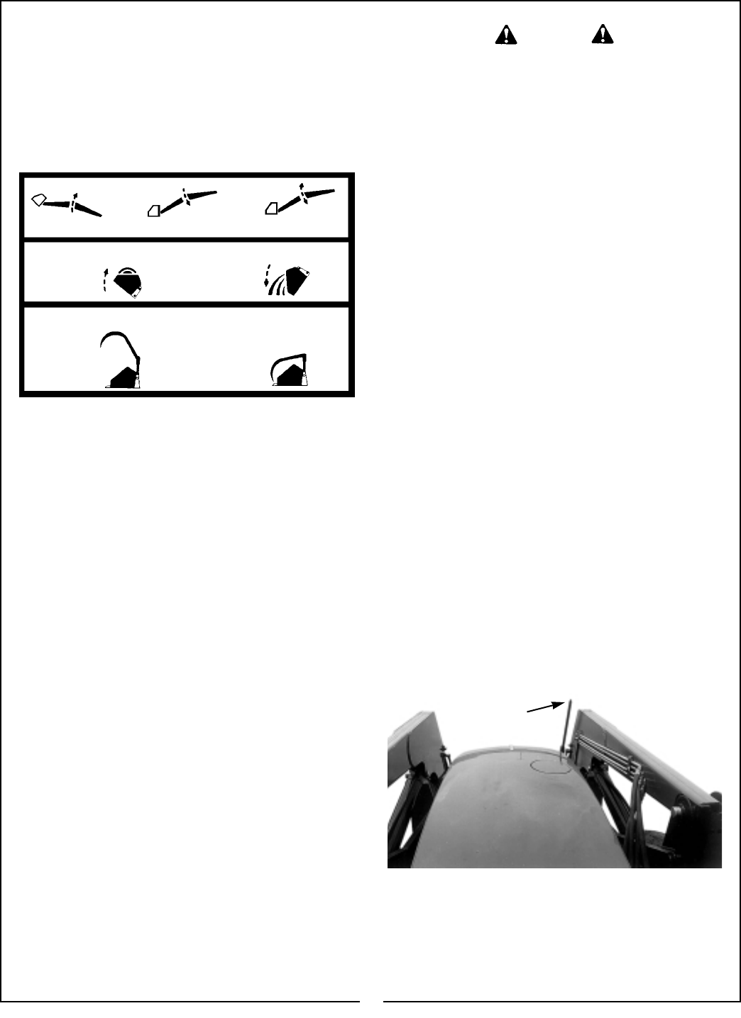
If your loader utilizes a loader mounted control valve
equipped with 2 or 3 control handles or tractor
remote valve equipped with 2 or 3 control handles, it
will function as described in Figure 3.
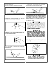
Lift Cylinder Circuit
Pull the handle
back to raise unit
Push the handle
forward to lower unit
Push handle full forward
to activate float position
Attachment Cylinder Circuit
Pull the handle
back to roll
back attachment
Push the handle
forward to
dump attachment
3rd Cylinder (optional) Circuit
Pull the handle
back to open
assembly
Push the handle
forward to close
assembly
Figure 3
NEUTRAL POSITION
The loader external valve provided by Bush Hog has
a “neutral position” which prevents movement of the
loader or attachment. When the control handle is
manually released from the work position, the valve
spool will return to the neutral position.
FLOAT POSITION
The loader external valve provided by Bush Hog has
a “float position” incorporated into the lift cylinder cir-
cuit which allows the loader to float. This float fea-
ture is important for satisfactory operation when
scraping, sweeping, leveling, or any job where it is
necessary to follow the contour of the surface. To
activate the float position, lower the bucket or
attachment and push the control handle all the way
forward into detent. The valve will stay in float detent
position until the operator manually pulls the control
handle out of detent position to deactivate float.
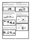
INITIAL LOADER OPERATION
Before operating the loader, fully raise and lower the
boom two or three times. Then raise the loader
bucket approximately four (4) feet above the ground
and cycle the bucket cylinders two or three times.
Lower the bucket or attachment to the ground.
Check the tractor hydraulic fluid level and fill as
required. Refer to the tractor Operator Manual for
the proper hydraulic fluid and the correct hydraulic
fluid level.
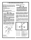
CAUTION
BEFORE LEAVING THE TRACTOR SEAT,
LOWER ATTACHMENT OR LOADER BOOM
TO GROUND, STOP ENGINE, LOCK
BRAKES, RELIEVE HYDRAULIC PRESSURE,
AND REMOVE KEY.
IMPORTANT: Always keep the cylinders in a
retracted position when the loader is not in use
to guard against rust and contamination which
may cause damage to the cylinder rods and
hydraulic system.
REMOVING AIR FROM HYDRAULIC SYSTEM
Repeat raising and lowering the loader boom and
bucket operations until all the air is removed from
the system and the system responds properly.
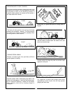
HOSE IDENTIFICATION
Check if loader functions as shown and described in
Figures 2 and 3. Then install colored nylon ties, one
color per each circuit. Locate nylon ties so one is
attached to male side of quick coupler and one is
attached to female side of quick coupler. This will
allow easy identification of loader circuits when
mounting and dismounting loader.
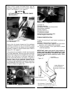
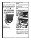
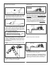
BUCKET LEVEL INDICATOR
BLI (bucket level indicator) rod has been preassem-
bled to loader linkage pin at the factory.
BLI (bucket level indicator) must be adjusted during
initial loader set up. Adjust the BLI as follows:
Position the bucket level on the ground. Loosen the
BLI clamp holding the BLI tube, and align the BLI
tube so that it is flush with end of the BLI rod, then
retighten BLI clamp. When operating loader, use the
attachment cylinder controls to align the BLI rod so
that it is flush with the end of the BLI tube. This will
inform the operator that the bucket and/or attach-
ment bottom is level with ground. Refer to Figure 4.
Figure 4
Bucket Level
Indicator
13