


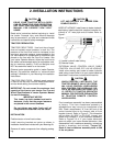

2. INSTALLATION INSTRUCTIONS
9
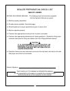
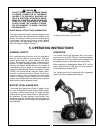
CAUTION
EQUIP YOUR TRACTOR WITH A ROPS
CAB OR FRAME FOR YOUR PROTECTION.
SEE YOUR TRACTOR/ROPS OPERATOR
MANUAL FOR CORRECT SEAT BELT
USAGE.
Read entire instructions before beginning to install
the loader. Personal injury and machine damage
may be prevented if you read and understand these
instructions and special safety messages.
TRACTOR PREPARATION
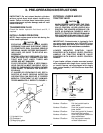
TRACTOR FRONT TIRES - Use front tires of equal
size and maintain equal pressure in each tire. The
pressure of the front tires must be increased to the
maximum approved pressure recommended by the
tire manufacturer to compensate for additional load
placed on the tires with the Front End Loader. See
your tractor Operator Manual. Adjust the front tires to
the widest recommended setting on adjustable mod-
els for maximum stability. Front end weights must
NOT be used while loader is on the tractor.
Observe tractor preparation guide in loader Operator
Manual. Pay particular attention to “minimum tread
settings” information in your Mounting Kit Installation
Instructions.
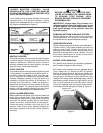
TRACTOR REAR TIRES - Maintain equal pressure
in each of the rear tires. Use the widest recommend-
ed rear wheel setting for maximum stability.
IMPORTANT: Do not exceed the maximum load
capacity of the tires on your tractor. See Tire and
Wheel Specifications in tractor Operator Manual
for more information.
INSTALLATION
Position tractor on level hard surface.
Install mounting brackets on tractor as shown in
Installation Instructions included with your Mounting Kit.
Remove all loader components from shipping packag-
ing.
IMPORTANT NOTICE
This loader has both standard and metric
fasteners. Verify that the proper fasteners
are placed in the correct locations.
Do not tighten any bolts firmly until all
components are attached onto the tractor.
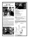
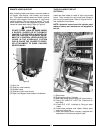
(1) Loader hydraulic steel tubing.
(2) Remote hoses.
EXTERNAL VALVE, CONTROL VALVE, CABLE
CONTROL VALVE AND PFC VALVE HOOKUP:
Install valve working port hoses to loader hydraulic
steel tubing. Install valve kit to your tractor/loader as
described in instructions included with these kits.
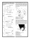
Front crossbrace assembly has been preassembled
at factory. This front crossbrace assembly is
adjustable and may have to be re-adjusted in the
field. Check measurement “A” from the front of the
center bracket tube to the forward side of front
bracket channel. Refer to Figure 2. This dimension
will be either 48-15/32” or 53-15/32”. Inspect your
loader and compare it to the subframe assembly.
Refer to Figures 3 & 4. If your loader dimension
does not match your tractor bracket dimension, then
disassemble front crossbrace assembly, relocate as
shown in drawings, and reinstall. Torque 3/4”
Grade 8 front crossbrace assembly bolts to 380
ft. lbs. six places.
Figure 1
HOSE KIT HOOKUP: Install hoses to loader hydraulic
steel tubing. Install male quick couplers (customer fur-
nished) to 1/2” male pipe ends of hoses. Refer to
Figure 1.
CAUTION
LIFT AND SUPPORT ALL LOADER COM-
PONENTS SAFELY.
CAUTION
WHEN PROPERLY INSTALLED, THE
TRACTOR REMOTE VALVE OR EXTER-
NAL VALVE CONTROL LEVER/LEVERS
WILL CONTROL THE HYDRAULIC CIR-
CUITS AS DESCRIBED ON PAGES 12 &
13. REFER TO TRACTOR OPERATOR
MANUAL FOR FURTHER EXPLANATION
OF TRACTOR REMOTE CONTROL
LEVER/LEVERS.