


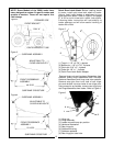
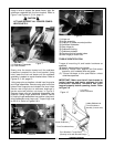
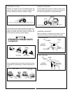
Using a hoist to support the loader frame, align the
subframe crosstube with the front bracket. Refer to
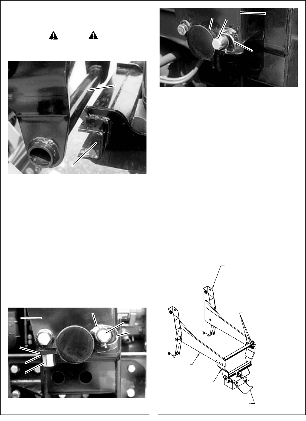
Figure 7 and Figures 2, 3, & 4, page 10.
CAUTION
LIFT AND SUPPORT ALL LOADER COMPO-
NENTS SAFELY.
2
1
(1) Subframe Crosstube.
(2) Front Bracket.
Slowly drive the tractor forward until the subframe
crosstube is seated into the front bracket. Using
hoist, lower the front end loader until the subframe
assembly is seated on center bracket tubes. Refer to
Figures 2, 3, & 4, page 10.
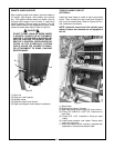
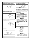
Using snap pins as handles, reinstall rear hinge pins
and hinge assemblies. Remove snap pins from outer
holes of rear hinge pins and reinstall into inner holes.
Secure rear hinge pins to subframe bushings in
loader mounted position as shown in Figure 8.
Remove hinge nuts and hardened flatwashers from
eyebolts. Swing hinge assemblies forward. Secure
by locking hinge assemblies into position using hard-
ened flatwashers and hinge nuts. Torque hinge nuts
to 200 ft. lb. Refer to Figures 8 & 9.
FIGURE 8
7
2
4
1
6
3
5
8
9
7
3
Figure 9
Figure 7
(1) Hinge nut.
(2) Hinge assembly.
(3) Snap pin in loader mounted position.
(4) Hardened flatwasher.
(5) Rear hinge pin.
(6) Subframe bushing.
(7) Subframe pedestal.
(8) Center mounting bracket tubes.
(9) Rear hinge pin outer hole.
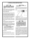
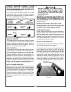
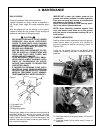
TORQUE IDENTIFICATION
Torque all mounting kit and loader hardware as
specified.
(A) Identify hardware size and grade.
(B) Refer to Torque Chart, page 43 and find correct
torque for your hardware size and grade.
(C) Torque hardware to this specification unless
otherwise specified.
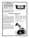
IMPORTANT: Make sure that all front bracket to
tractor hardware and loader subframe to front
crossbrace assembly hardware has been
torqued properly before operating loader. Refer
to Figure 10.
Loader Subframe
Loader Subframe to
Front Crossbrace
Asembly (3 each side)
Loader Subframe
Front Crossbrace Assy.
Front Bracket to Tractor Bolts
(Quantity varies with Bracket Design
Figure 10
11