


Bird Model 4391A Power Analyst
28
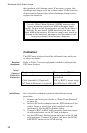
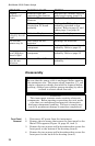
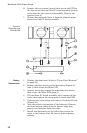
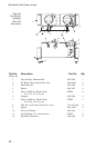
6. Remove the two screws (item 4) that secure the PCB to
the line section then pull the PC board assembly (item 3)
away from the line section subassembly. Remove the
spacers (item 2).
7. Remove keying beads (item 1) from the element wiper
contacts on the PC board assembly.
Battery
Replacement
1. Remove the front panel (refer to “Front Panel Removal”
on page 24)
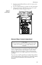
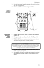
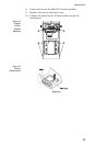
2. Remove the four screws and lock washers (Figure 22,
item 1) that secure the Main PCB.
3. Loosen, but do not remove the remaining two screws
that secure the Main PCB (item 2).
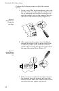
4. Tilt the Main PC board assembly up to expose the bat-
teries then tighten the two screws to secure the PCB.
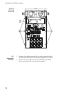
5. Unfasten the velcro strap and remove it from the D-ring.
(Figure 23).
6. Note the polarity orientation of the batteries. Remove
the three battery tubes from the battery clips then
remove two batteries from each tube.
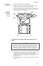
7. Install new batteries into the tubes then secure the
tubes in the battery clips. Be sure to observe proper
polarity.
Figure 21
Removing Line
Section PCB